-
-
June 11, 2018 at 11:25 pm
RD2016
SubscriberHey all,
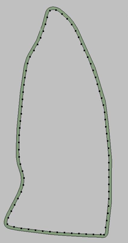
I have an issue with using the Imported Displacement feature in Mechanical. Briefly, I'm attempting to model the motion of a wall by using the External Data module in Workbench, and then import this into Mechanical. I will map x-y data points (not mesh nodes) onto my Mechanical mesh, and use the Imported Displacement option to move. The Mechanical model is a 3D wall, approximately 1 mm in thickness and extruded out by 1 mm.
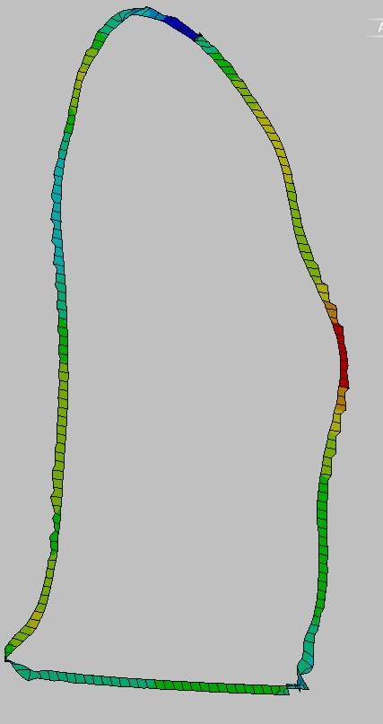
I can import my data points very easily, as shown in the first figure. I have appropriately calculated the displacement and have set this up in Mechanical. My issue lies in the mapping function. Regardless of what settings I use, when I run my simulation the results show a highly distorted mesh (second figure). Any recommendations would be much appreciated!
I understand this isn't a lot to go on, so I will be more than happy to provide further details about my setup.

-
June 12, 2018 at 12:18 am
peteroznewman
SubscriberHey,
It will be much easier to try things if you prepare a zip file that contains the external data and the folder that has your ANSYS Workbench file and _files folder. You can attach zip files to your posts using the Attach button as long as the file size is < 120 MB.
Have you considered a beam model that would just connect the points?
-
June 12, 2018 at 1:01 am
RD2016
SubscriberI've attached the archived simulation. It should contain the geometry, and three .csv files that are within the External Data module.
I have not considered a beam model because this simulation will eventually be 1-way FSI. My goal is to use Mechanical to simulate wall motion which will then be transferred over to Fluent. As of right now, I am unsure that the beam model will be able to support this, though I could be wrong.
Â
-
June 12, 2018 at 6:47 pm
RD2016
Subscriber Hi, just checking in to see if you had any luck with this.
-
June 12, 2018 at 9:05 pm
peteroznewman
SubscriberI am a novice at External Data. I had a look at your model and reproduced the issue, but I have no idea how to resolve it. Hopefully another member who has more experience with this can help you.
Good luck,
Peter -
June 13, 2018 at 4:45 pm
RD2016
SubscriberThanks anyway, I really appreciate you taking the time to look at my stuff. Does anyone else know of a potential fix for this?
-
June 13, 2018 at 5:25 pm
peteroznewman
SubscriberWhere did the deformations come from that you are importing? Can you just apply loads and supports to the structure in Mechanical to get the displacement calculated by ANSYS that is a close approximation of what you were importing.
-
June 13, 2018 at 5:33 pm
RD2016
SubscriberUnfortunately, no. Long in the short, I'm simulating wall motion of a very specific deformation (heart contraction and relaxation taken from MRI scans). The only way to reproduce it is to tell Mechanical which nodes move at which time. This isn't a typical Mechanical simulation, and like I said the only reason I care about this is to use it to move the wall in Fluent. Usually, other investigators code the movement of nodes in Fluent using a UDF, and then allow for the solver to remesh as it sees fit. I'm not very good at coding, but I know how to use Mechanical, so I'm circumventing that problem.
Â
-
June 13, 2018 at 6:11 pm
peteroznewman
Subscriber
The only way to reproduce it is to tell Mechanical which nodes move at which time.
Not true. I was at a conference last week and there were many talks on simulations of the blood flow through a human heart that is contracting and relaxing by electrical stimulation of simulated muscles. Here is one paper. (repaired link)
-
June 13, 2018 at 7:27 pm
RD2016
SubscriberThanks for the info. Unfortunately, the link for the paper is dead. I skimmed through the webinar (Simutech is a great company, and I've used a lot of their resources before) but it seemed like they were mainly focused on developing FDA approved devices and implants with rigid structures, not necessarily modeling cardiac wall motion. I'll watch the entirety later tonight.
Utilizing an electromechanical FSI model (which is what I'm assuming they were using at the conference) can be just as accurate, albeit more complicated. I confess that I am unfamiliar with the specifics of the setup, though, and it seems like most investigators tend to follow the image-based method of cardiac simulation (using MRI data to induce wall motion) nowadays. If it's not too bold, what conference did you go to? I'd like some more info about it.
I think I found a setup for my Mechanical issue that might work out. By using a coarser mesh, and Distance Based Average for the Mapping, along with setting the number of points to 7, I was able to get smooth motion. I don't necessarily have a reason why this works yet, I found this through trial-and-error.
Thanks!

Â
-
June 13, 2018 at 7:47 pm
peteroznewman
Subscriber Try this link for the paper.
I went to the CAASE18 / NAFEMS conference in Cleveland. Here is the link for the conference. (repaired).
-
June 13, 2018 at 7:58 pm
RD2016
Subscriber The link for the conference isn't working, unfortunately, but I'll look it up using the info you provided.
I've actually heard of the Living Heart Project, and have a lot of high hopes for it. I didn't think it used ANSYS for it's fluid model, though. I know it used ABAQUS for the solid/electrical simulation.
Thanks again for everything you've provided.
-
- The topic ‘External Data – Mapping Data Points in Mechanical’ is closed to new replies.
-
6535
-
1906
-
1463
-
1311
-
1022
© 2026 Copyright ANSYS, Inc. All rights reserved.