-
-
July 5, 2024 at 3:24 am
Mo
SubscriberHi,
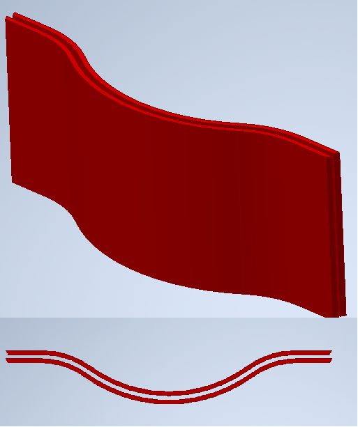
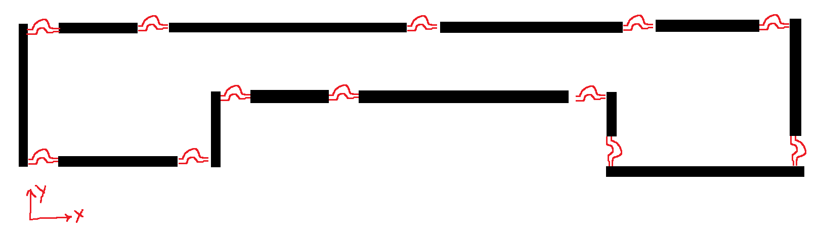
I have an Omega type expansion joint looks like attached connecting two beams together. I have number of these expansion joints in the assembly and to decrease analysis time in my FEA, I ‘ve decided to model these expansion joints as Springs. I tried to find the stiffness of the expansion joint, but not sure how to do it. When I introduce an expansion increments in x direction to one side of an expansion joint on the Fixed side I get Fx, Fy, and Mz. Same for Y direction, as when I introduce y direction displacement increments, I get F’x, F’y, M’z on the Fixed side. In this case how can I define joints between to beams as spring?
Â
Â
Â
-
July 10, 2024 at 7:08 am
Ashish Khemka
Forum ModeratorHi,
How much time are these bodies increasing? Are you modeling them as solid bodies? What if you use shell elements to represent these bodies? Using shell elements seems a good approach.
If you want a replacement then bushing joints can be a choice but again you will need to find the stiffness in each direction for translation and rotation.
Regards,
Ashish Khemka
-
- The topic ‘Expansion joint to Spring’ is closed to new replies.
- The legend values are not changing.
- LPBF Simulation of dissimilar materials in ANSYS mechanical (Thermal Transient)
- Convergence error in modal analysis
- APDL, memory, solid
- How to model a bimodular material in Mechanical
- Meaning of the error
- Simulate a fan on the end of shaft
- Nonlinear load cases combinations
- Real Life Example of a non-symmetric eigenvalue problem
- How can the results of Pressures and Motions for all elements be obtained?
-
3892
-
1414
-
1241
-
1118
-
1015
© 2025 Copyright ANSYS, Inc. All rights reserved.