-
-
April 15, 2024 at 8:17 pm
S.S.S.ShankaVasuki
SubscriberHi everyone,
I am trying to simulate the hydrodynamic response of two floating blocks connected to each other as shown in the attached images. Each of the blocks are of dimensions 37.5m (L) x 60m (W) and the gap between the two blocks is 0.5m. I have used the hinged joint to make the connection between the two blocks. As of now, I have not specified any stiffness for the joints for a simple analysis. I am trying to do both frequency and time domain analysis. The frequency domain analysis using hydrodynamic diffration did not show any errors where as the in the hydrodynamic response analysis, there were a few warnings along with the error - " HYDRODYNAMICALLY INTERACTING STRUCTURES HAVE MOVED TOO FAR FROM ANALYSIS POSITION MOVEMENT EXCEEDS 75% STOPPED AT TIME = 0.00."
I have tried the following to elimate this error:
a. I have checked the selection of the blocks after the joint has been established as it seems to be in order as per the image I have attached.
b. Also, I have set the water size of X = 3000m and Y = 840m. So I am assuming that it is sufficiently long for a 10s simulation for a regular wave whose wave height is 0.1m and the wave frequency is 0.71826 rad/sec.
c. I also tried to added deactivated freedoms for both the blocsk in X, Y, Ry and Rz directions as I am interested in the heave (z) and pitch (Rx) response only.
d. I have also refined my mesh with an element size of 0.5m, connection tolerance of 0.01m as shown in the attached image.
Despite all these tries, I have not been to resolve this error. It would really really helpful if someone can help me out with this!
Thank you!
-
April 17, 2024 at 11:14 am
Shuangxing Du
Ansys EmployeeIn the time domain analysis, the relative distances between the diffraction elements among the hydrodynamic interaction structures are checked. The error will be issued if the distance changes are large.
As shown below, please make sure the hinge connection points on the structures are at the middle of the gap. It may also improve if you could set the surfaces in the gap as non-diffraction surfaces.
Do you need to define some fenders in the gap to prevent the structures from collision?
-
April 17, 2024 at 1:29 pm
S.S.S.ShankaVasuki
SubscriberHi,
Thank you for your response. Just to give you more context on the problem I am trying to solve. Basically I want to estimate the hydrodynamic response of a flexible floating structure. Hence this flexible structure is broken into multiple rigid blocks connected together with hinges. Ideally there would be around 8-10 blocks connected together in total. But to just get a hang of solving this problem, I am just using two blocks as a starting point.
I have tried two things:
- Original Case: This is the problem that I have initally mentioned in my post. The image below shows my model setup and the locations of the connection points I have used. Here all the surfaces are diffracting and the error I get is this - " HYDRODYNAMICALLY INTERACTING STRUCTURES HAVE MOVED TOO FAR FROM ANALYSIS POSITION MOVEMENT EXCEEDS 75% STOPPED AT TIME = 0.00."
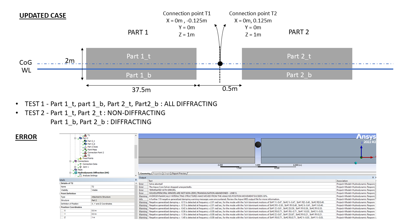
2. Updated case: This is the latest simulation I ran incorporating your suggestions of having the 2 hinge connection points (T1,T2) at the middle of the gap. With this I ran two simulations, one where all the surfaces are diffracting and second with only the surfaces in contact with the water as diffracting. You can get a better idea of this setup with the image below. In both simulations the old error goes away and there is a new error which says - " SOLVEG:PRINCIPAL MINORS ARE NOT NON-ZERO,TRIANGULISATION ABANDONED - LINE13."
Please let me know on how to solve this problem. I have actually spent a lot of time figuring this out without any success. Any help would be great! :)
Thanks!
-
April 17, 2024 at 2:37 pm
Shuangxing Du
Ansys Employee(1) As the original structure is flexible with bending stiffness, when you define a hinge (hinge axial direction is along y-aixs), you should define the proper bending stiffness of the hinge.
(2) there should be no gap between the splitted structural blocks (or very small gap to allow bending deformation between the structural blocks). Not sure why there is a 0.5m gap between these two blocks, as the moulded depth is just 2m.
(3) there is no need to define the surfaces of the blocks between the cutting, as shown the yellow parts below
-
April 17, 2024 at 2:53 pm
S.S.S.ShankaVasuki
SubscriberHi,
Thank you for your quick response. Addressing your points in order:
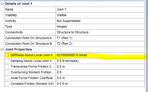
(1) Regarding the stiffness of the hinged joint, I do not see the option to enter the stiffness about the y-axis. It only shows me the option to enter the stiffness about the x-axis as shown in the figure. Does that mean that my connection points are wrong?
(2) I understand that having 0.5m gap for a block depth of 2m is quite high. But I assume that there is a small gap needed so as to have hinged joint between them right? do you suggest to reduce the gap size to lets say 0.05m?
(3) I am a little confused with this suggestion. I have not defined the surfaces that you have marked in yellow.
The main question that I still have is:
(A) what should be the location of both my connection points? Is this connection points in the updated case alright or do I have to change them to something else?
Thank you for the help!
-
April 17, 2024 at 3:10 pm
Shuangxing Du
Ansys Employee(1) As your hinge is defined along the global y axis, there is a need to define the bending stiffness along the global y-axis, which is the x-axis in the hinge local joint axis. Your definition is correct.
(2) It is up to you to make this gap to be smaller or not. It may affect the accuracy of the results, as there is no “gap” between the two parts of the original flexible structure.
(3) It is great if there were no such surfaces.
(4) T1 (Part1) at (0.0, 0.0, 1.0) and T2 (Part 2) at (0.0, 0.0, 1.0) will be fine, and the hinge axis is along global y-direction. It could be better to let the joint's vertical location be on the bending neutral axis.
(5) please check the masses and moments of ineria of the two parts are defined properly.
-
- The topic ‘Errors with multi-connected bodies using AQWA’ is closed to new replies.


-
3472
-
1057
-
1051
-
940
-
902

© 2025 Copyright ANSYS, Inc. All rights reserved.


