-
-
August 18, 2022 at 1:02 pm
javat33489
SubscriberHi all.
I'm modeling metal cutting.
There are no chips when cutting.
I am using the Johnson Cook model and ADD_EROSION.
I want to apply MAT_NONLOCAL map. An error occurs during initialization:
Why?
What are the main parameters that must be in order for chips to appear when cutting?
Materials:
I have a good mesh of 100 mm by 100 mm thick, the thickness of the dies is 1 mm.
-
August 19, 2022 at 4:01 pm
Reno Genest
Ansys EmployeeHello,
What is L set to in *MAT_NONLOCAL? It look like you are including 302500 elements in the search which is way too much and this is why you ran out of memory. The L parameter should be set to include only a few elements. Refer to the LS-DYNA user manual for more information:
Also, your elements have a high aspect ratio and so the quality could be improved.
I would simplify the model for now and remvove the *MAT_NONLOCAL. To see chips, you need material failure to occur around a group of elements. If this does not occur, the elements just get deleted when they fail and you never see chips.Â
An alternative to classical finite elements is to use particle methods to model metal cutting. With particle method, the bonds between particles break when the material fails and so you don't have mass loss (as with regular FEM) and you can see chips right away. Have a look at the following examples:
https://www.dynaexamples.com/efg/metal-cutting
https://www.lstc-cmmg.org/cutting
https://www.lstc-cmmg.org/spg
Â
Note that a higher CPU cost is associated with particle methods.
Â
Let me know how it goes.
Â
Reno.
-
August 19, 2022 at 6:17 pm
javat33489
SubscriberThanks for the answer.
 >>What is L set to in *MAT_NONLOCAL?
>>Refer to the LS-DYNA user manual for more information
Yes, of course, I read everything and made the standard parameters
>>To see chips, you need material failure to occur around a group of elements. If this does not occur, the elements just get deleted when they fail and you never see chips.Â
At first I would like to solve everything by the Lagrange method, and then move on to particles. Please tell me what settings in the maps need to be done? I tried many options, nothing worked, the material is always deleted.
>>An alternative to classical finite elements is to use particle methods to model metal cutting. With particle method, the bonds between particles break when the material fails and so you don't have mass loss (as with regular FEM) and you can see chips right away. Have a look at the following examples
Yes, of course I have seen them all. I looked all over youtube. I have also read many books and works. But nowhere was it said how to set up the material for chip separation.
I can attach a k-file, can you see it? Or could you answer how to set up the maps so that the chips appear?
-
-
August 19, 2022 at 6:29 pm
Reno Genest
Ansys EmployeeHello,
Â
Try setting L to a smaller value and try again. The L value is probably too large compared with the mesh.
With the Lagrangian method, elements get deleted as failure occurs and so it will be difficult to see chips being formed and fly away. It is probably best to use the particle method if you want to see chips.
Have a look at dynalook.com and search for metal cutting papers. We don't provide material input parameters. It is your responsibility to get them. You need parameters to model material failure. You can test the material yourself or maybe find something in the literature.Â
At last, as an Ansys employee, I am not allowed to download your model. You can still post it here so that other users can help you.
Let me know how it goes.
Â
Reno.
-
August 19, 2022 at 7:07 pm
javat33489
SubscriberI will look there again. The papers on this site do not specify how to set up material failure. Can you tell me what card it's configured in? I will do the settings myself. I just need to know which cards to look at. In this case, I myself will bear the responsibility, I will do many tests and compare them.
-
-
August 19, 2022 at 7:51 pm
Reno Genest
Ansys EmployeeHello,
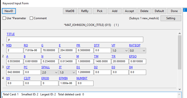
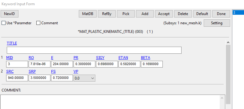
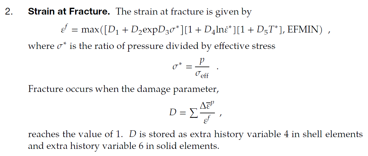
There are many ways to include failure. Many material models (*MAT_015 included) have material failure built-in. For metal failure, plastic strain at failure is commonly used. In *MAT_015, you can have failure strain a function of triaxiality (state of stress), strain rate, and temperature using the D parameters.
Â
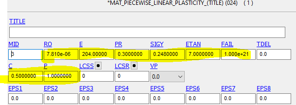
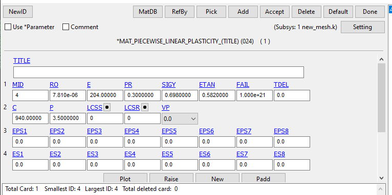
You don't need to have such a complex failure to begin with. *MAT_024 is commonly used to model metals and you can define a simple plastic strain at failure using the FAIL parameter. Once you get it working, you can add complexities (triaxiality, strain rate, or temperature effects) to be more accurate in your failure prediction. Here is a good video on *MAT_024:
https://www.youtube.com/watch?v=J5Qjj_9Sot0
https://www.dynamore.de/de/download/presentation/2020/copy_of_dynamore-express-good-old-mat_024-a-review-of-ls-dyna2019s-most-popular-material-model
Â
Also, you will find some examples of material models (*MAT_224; tabulated Johnson-Cook) for some metals used in the aerospace industry on the Aerospace Working Group:
https://awg.lstc.com/tiki-index.php?page=Material+Parameter+Sets
You will find the LS-DYNA parameters (.k file) and also reports on how they developed the material model. This is very instructive.
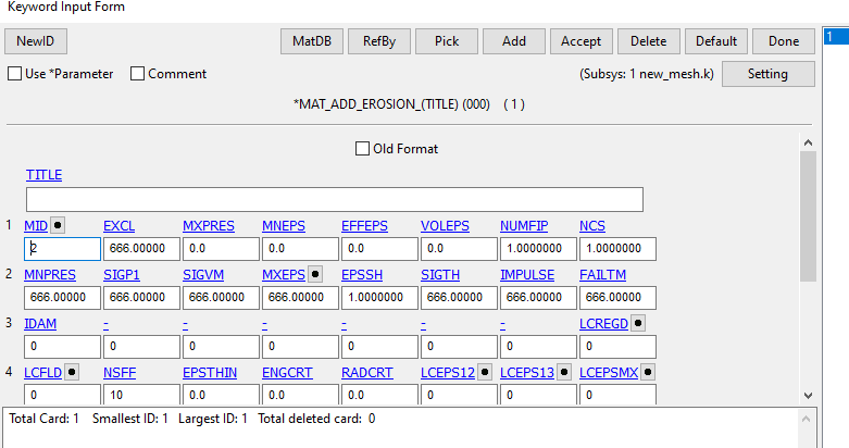
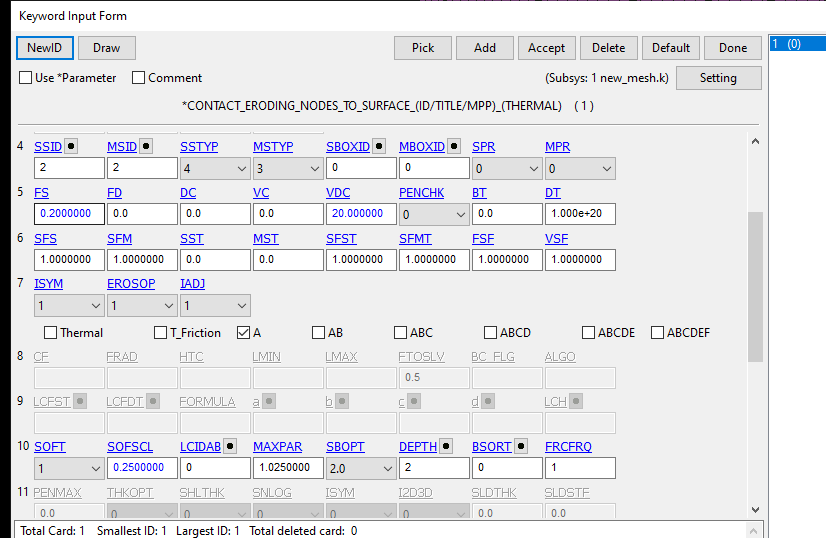
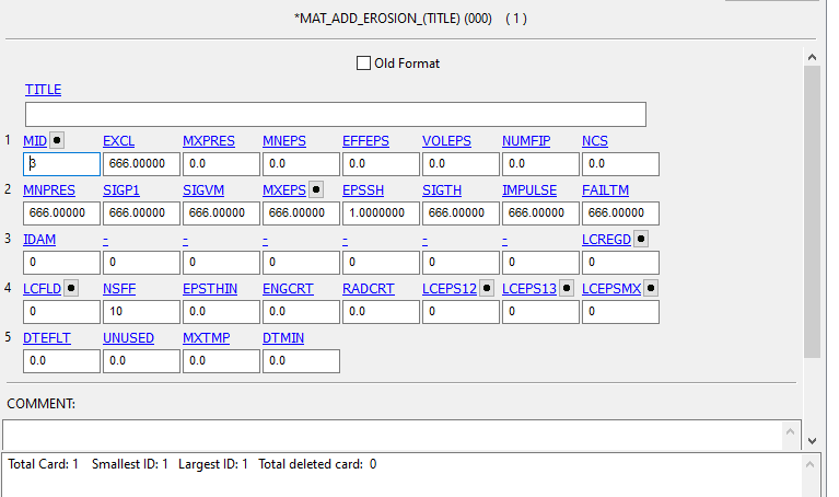
At last, you could use *MAT_ADD_EROSION or *MAT_ADD_DAMAGE_GISSMO to add failure to your model. In the end, you want to be able to reproduce experimental test data. If you are able to achieve it, then your model should be ok.Â
Â
Let me know if this helps or not.
Â
Reno.
-
August 20, 2022 at 9:14 am
javat33489
SubscriberI have already tried using MAT_24 and got the same result. The material was removed. I'll try again. Thank you.
Most of the papers and tutorials contain MAT_15. There are a lot of ready-made experimental data for him. I'd like to understand how to set it up to display shavings.
Shavings should appear without *MAT_ADD_EROSION or *MAT_ADD_DAMAGE_GISSMO maps, they are additional to clarify the calculation.
Thank you for your responses.
-
August 20, 2022 at 10:07 am
-
-
August 20, 2022 at 10:39 am
-
August 22, 2022 at 7:38 pm
-
August 22, 2022 at 7:39 pm
-
August 22, 2022 at 7:39 pm
-
August 22, 2022 at 7:54 pm
Reno Genest
Ansys EmployeeHello,
With traditional FEM and failure, the elements get removed. So, most likely you will never see chips being created unless you are lucky and remove big chunks of material at a time. Element will get deleted when material failure occurs, so what you observe is what is expected.
I would try with the SPG method:
https://www.lstc-cmmg.org/cutting
Â
Let me know how it goes.
Â
Reno.
Â
Â
-
August 23, 2022 at 5:17 pm
javat33489
SubscriberIt's a pity. I wanted to get chips in Lagrange
-
-
August 23, 2022 at 5:28 pm
Reno Genest
Ansys EmployeeÂ
Hello,
The only way to get chips with Lagrange mesh is to create big chips; the tool has to be at least under the first row of elements:
https://www.youtube.com/watch?v=FcO1–wQJYU
https://www.youtube.com/watch?v=6gJhB8yKNkE
Otherwise, the particle method is a better choice.
Â
Reno.
Â
Â
-
August 23, 2022 at 5:54 pm
javat33489
SubscriberThe first video is not working. The second video is an excerpt, the whole video costs 150 euros from the author.
-
-
August 24, 2022 at 12:52 pm
-
- The topic ‘Error in MAT_NONLOCAL’ is closed to new replies.
-
6465
-
1906
-
1458
-
1308
-
1022
© 2026 Copyright ANSYS, Inc. All rights reserved.


