Greetings all,
I am using Fluent 2021R1 and am required to simulate slurry based erosion in pipes using UDFs in transient state. In attempts to do so, I have been facing the problem that the “erosion contours” presented by Fluent appear as a distribution of discrete spots rather than contours of continuous regions (examples below) for any of the UDFs that I use. Apparently, the problem responsible for causing such discrete erosion region is also responsible for causing the plots of the extracted erosion values to be of curves with abrupt variations. This is a problem because the expected plot and contours should represent a rather steady and gradual increase in erosion when the top centreline of the elbow is considered according to the experimental results. It seems that the data requires averaging of some sort, but I am unable to figure out based on which parameter exactly and how. So, I would appreciate it if any insight can be given on how to achieve continuous erosion contours and hence a linear/concave curve when applying UDF. I understand that it may be difficult to provide a generic solution that will be applicable for any UDF, so I have provided below the UDF that I had prepared based on the Oka model as presented in Reference 1. It would be helpful if anyone can provide suggestions based on the provided UDF, which will also help me understand modifications that need to be made for any other UDFs that I need to apply. I also understand that one may require to know additional information regarding the parameters to help me solve this problem, so please let me know what information would be sufficient to provide.
Also, if it helps to know, I have made some observations regarding this problem…The discrete appearance of the "erosion contours" / the abruptly changing plot which I find when I apply my UDFs in transient state is also visible if the same case is run in steady state regardless of the type of erosion model used and whether it uses a UDF or is in-built. However, if the case is run in transient state but without the UDF, i.e. the erosion is computed based on Fluent's in-built erosion models in transient state, the "erosion contours" are continuous regions of erosion and the data plot is a slightly concave curve as desired. I have attached below example images of the contours achieved in the different cases. This implies to me that the continuous nature of the contours maybe due to a time factor that is involved by default in the transient state and the in-built erosion models but is missing within my UDF. I actually did attempt to incorporate the time unit in my UDF code by utilizing the particle mass flow rate (kg/s) but it did not seem to help. So, any advice on this case would be appreciated.
My UDF code based on Oka model...
#include "udf.h"
#include "math.h"

DEFINE_DPM_EROSION(Oka, tp, t, f, normal, alpha, Vmag, mdot)
{
real E_alpha, g_alpha, E_90, Hv, n1, n2, k1, k2, k3, K, a, b, V_ref, D_ref, D;
Hv = 2.01; /*GPa*/
n1 = 0.79;
n2 = 1.34;
k1 = -0.12;
k2 = 2.35;
k3 = 0.19;
K = 50;
a = 0.0071;
b = 0.4;
V_ref = 104; /*(m/s)*/
D_ref = 0.000326; /*m*/
D = 0.00045; /*m*/
g_alpha = (pow((sin(alpha)),n1)) * (pow((1+(Hv*(1-(sin(alpha))))),n2)); /*impact angle function, angle in radians*/
E_90 = (K*(pow((a*Hv),(k1*b))))*(pow((Vmag/V_ref),k2))*(pow((D/D_ref),k3)); /*erosion at an impact angle of 90 degrees*/
E_alpha = (g_alpha)*(E_90); /*erosion at an arbitrary angle*/
F_STORAGE_R_XV(f, t, SV_DPMS_EROSION, EROSION_UDF) = E_alpha;}
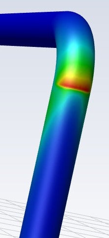
The desired erosion contours only achievable with Fluent's in-built erosion models run in transient state...
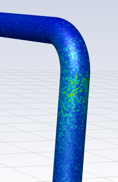
The achieved but undesired erosion contours when any UDF is applied and when any erosion simulation is run in steady state...
Thank you.


