
TAGGED: kinematic-mount, meshing, transient-structural
-
-
November 9, 2021 at 8:38 pm
rbaheti
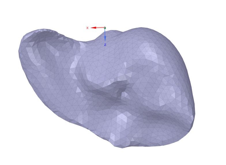
SubscriberI'm working on an irregular object and implementing a kinematic mount. Due to the irregular shape of the object the nodes don't fall on the plane. Is there a way to ensure the mesh nodes are created on the plane (and the surface of the body - check image for reference)
I came across something called hard point but can't find any concrete implementation method online. Can this be used for the problem I'm trying to solve - If so, then how?
November 9, 2021 at 10:09 pmpeteroznewman
SubscriberOne way to get nodes at specific fixed locations is to open the Geometry in SpaceClaim or other CAD system and split the face to create a vertex on the surface. You need two planes to create a vertex on a sphere at one point.
November 10, 2021 at 5:36 pmSubscriberCould you explain this is a bit more detail?
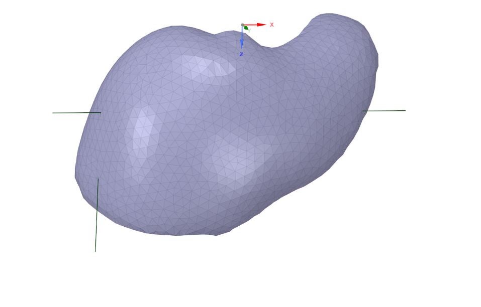
To elaborate on my problem - the object I'm working on is a STL file of an organ (image below). To implement the kinematic constraint I can need to give certain displacement constraints at a few nodes. These nodes are located depending on the way the mesh is created. Since I can only select nodes on the surface of the object - the likely hood that the points would form a 90-degree L-shape (rules of kinematic constraint) is highly unlikely. I tried to use the "skin surface" option on SpaceClaim to get split the entire object into 2 halves based on the lines drawn but no luck there (see image 2 - the lines are perpendicular and almost meet at the surface of the organ)
 Is it possible to create a few points/nodes on the surface of the object about which the mesh is created?
November 10, 2021 at 6:30 pmSubscriberA kinematic mount does not require that the three points form any kind of specific angle such as 90 degrees. The only requirement is that the three points are not colinear. If you pick any three points near the furthest extent in three directions, could even be directions 120 degrees apart, that is fine.
Were you successful obtaining a skinned surface? That generally consists of more than one face. Please show that.
November 10, 2021 at 8:38 pmSubscriberThanks for the clarification on kinematic constraint
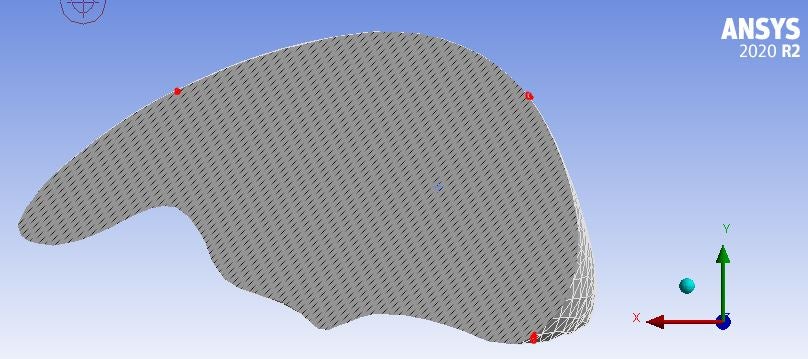
Regarding my implementation kinematic constraint: For example - Right now if I choose 3 non-colinear points as close to the XY plane (I can't get them to be exactly on the plane since the mesh won't create a node there exactly) there is a chance of artificial strain created due to the constraint-location mismatch i.e. if I give 0 displacement in Y and Z but the point is not exactly on the X axis w.r.t to the fixed point. I believe the easier option is to create a new coordinate system based on the 3 points selected and apply kinematic constraint based on the new coordinate system - this ensures "prefect" alignment. The same kinematic constraint will be implemented but in new directions. However, I don't know if it's possible - is it?
Regarding skinned surface - This method didn't work as I expected it to. I closed the sketch but it never created a new surface. Moreover, I'm not sure how this would be beneficial to what I'm trying to do.
November 10, 2021 at 11:00 pmSubscriberPick any three points on the body that are well separated, they define their own plane. The points don't have to be in the global XY plane. In the figure below, the point C does not have to be in any particular relationship to points A and B other that it can't be on the line AB. Point C can be anywhere. Create a local coordinate system using those three points. Point A is the origin, Point B is on the X axis and Point C defines the XY plane.
From thisreference. Figure 4 shows a 3-2-1 kinematic mount. The three constraints at point A prevent translations in X, Y, and Z, but do not preclude rotations about A. The additional constraints at B prevent rotations about Z and Y, and the constraint at C prevents rotations about X.
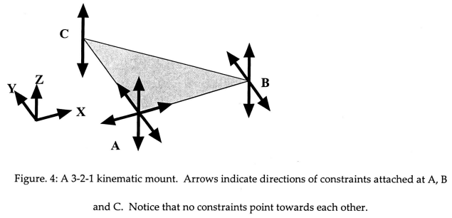 If the mounted object were to change its dimensions, due to differential thermal contraction with the base, or small machining errors, for example, point A would remain fixed, and points B and C would move freely towards or away from A along their unconstrained directions. It is this allowed free motion which is the key to making a mount kinematic. If another constraint were added, for example an additional X direction constraint at B, then the distance between points A and B would be fixed, and a dimension change in the object would produce a stress.
November 20, 2021 at 12:08 amSubscriberThanks for your help on the kinematic constraint problem.
When I try to implement it on the model shown in the original question, I use remote displacement to implement the boundary conditions (BC) and change the coordinate system to the new coordinate system made using the 3 points I selected. But when I use a simpler model like a cylinder, I can't select the node I want as a vertex so I can't use the remote displacement. I tried using the nodal displacement but I can't change the coordinate system from the default coordinate system i.e. Nodal Coordinate System.
Is there a way to change the nodal coordinate system to a new coordinate system or save a node on the curved surface of the cylinder as a vertex? Or maybe a 3rd option?
Viewing 6 reply threads- The topic ‘Ensuring mesh node passes through a particular point’ is closed to new replies.
Innovation Space Trending discussions
 Top Contributors
-
peteroznewman
 6450
6450 -
scabo
 1906
1906 -
Dennis Chen
 1457
1457 -
javat33489
 1308
1308 -
Shyam Prasad V Atri
1022
Top Rated Tags
© 2026 Copyright ANSYS, Inc. All rights reserved.
Ansys does not support the usage of unauthorized Ansys software. Please visit www.ansys.com to obtain an official distribution.
-


The Ansys Learning Forum is a public forum. You are prohibited from providing (i) information that is confidential to You, your employer, or any third party, (ii) Personal Data or individually identifiable health information, (iii) any information that is U.S. Government Classified, Controlled Unclassified Information, International Traffic in Arms Regulators (ITAR) or Export Administration Regulators (EAR) controlled or otherwise have been determined by the United States Government or by a foreign government to require protection against unauthorized disclosure for reasons of national security, or (iv) topics or information restricted by the People's Republic of China data protection and privacy laws.
