Energy error/hourglass error in a piston connecting rod crankshaft engine assembly Explicit Dynamics

TAGGED: autodyn, energy-error, explicit-dynamics, hourglass, hourglass-energy
-
-
December 21, 2020 at 6:57 pm
bobsik641
SubscriberHello all,
To begin with, this is not a typical hourglass/energy error problem, so please don't tell me to search the database. I contacted my local Ansys Elite Channel Partner, but they couldn't find the cause of the problem.
I am simulating an engine assembly. The piston, the pins and the crankshaft are rigid bodies, while the connecting rod and the bolts are flexible. I use bonded contact for the threaded connection and frictional contacts for all other contacts.
The first problem is the hourglass energy. I am using the stiffness formulation (Flanagan-Belytschko) for hourglass damping. I tried different coefficients, but every time the hourglass damping is much larger than the internal energy.However, no hourglassing is visible. Mesh refinement didn’t work, on the contrary- on a very fine grid, the hourglass energy was about 1500% of the internal energy!! The viscous formulation is not working at all. I see that the hourglassing is accumulated in the bolts and near the bolt holes. The grid is perfect, almost 100% hexahedral elements. I use mass scaling, since there are a few smaller elements. Max element mass scaling is ~10.
December 21, 2020 at 9:37 pmSubscriberI reran the case with almost no (vastly reduced) mass scaling. The hourglass energy was reduced 3 times, but it is still 3 times larger than the average internal energy.nDecember 25, 2020 at 5:23 pmSubscriberAny ideas?.December 28, 2020 at 10:59 pmChris Quan
Ansys EmployeeCan you use any text editor to open the admodel.prt file from the MECH folder of the project and then look at the material and part summary to identify the material or the part that has contributed the most to the hourglass energy?nJanuary 1, 2021 at 1:59 pmSubscriberThe hourglass energy is accumulated just everywhere ... When I ran the case with viscous damping, the regions near the screws and the screws themselves underwent hourglassing. I cannot identify a specific part based on the list because these codes C-10, C-11 etc. do not figure in the Workbench part list.n nI managed to eliminate the Energy Error. Instead of accelerating the mechanism from 0, I imposed an Initial Condition (values extracted from a separate Rigid Dynamics analysis). Anyway, the hourglass energy still greatly exceeds the internal energy... I will try to refine the grid to an absurd sizing, say 0.3mm (connecting rod length 300mm) and run the case on my university cluster.nnnHowever, another problem has appeared. I saw that the bonded contact was not enforced/detected properlyn
 so I changed the Maximum Offset from 1e-4mm to 0.2mm.Now the bonded contact is perfectly fine, however the general motion of the connecting rod is oscillatory. What could be the source of this problem? Should I use some damping?n
 n
January 1, 2021 at 2:15 pm
n
January 1, 2021 at 2:15 pmpeteroznewman
Subscriber@bobsik641, @cxquan, nI had one of the simplest models you can imagine, a tube rotating on its axis at a constant velocity. The hourglass energy built up to a huge value and began eroding the elements!nThe material is BRASS from the Explicit Dynamics category of Engineering Data. A solid tube has an initial condition of an Angular Velocity of -36.65 rad/sechttps://us.v-cdn.net/6032193/uploads/ZPD2ADBKHIV0/image.pngThe Remote Displacement ramps a rotation of -1800 degrees in 0.856 shttps://us.v-cdn.net/6032193/uploads/7W04WWY9H1HM/image.pngDoing the math on the angular velocity and the remote displacement, they both come out to be 350 rpm.https://us.v-cdn.net/6032193/uploads/JUQUOYIV8OZ4/image.pngI expect to see a simulation where the solid tube has an uneventful time rotating. Instead the tube erodes away. I understand there will be some stress from the small amount of centripetal force and some Poisson ratio effect, but I didn't expect this:https://youtu.be/hnCAjtntk9kWhat is wrong with this model? I know that @MAMIN219 wants to know the answer to this question. /forum/discussion/21391/thermal-aspects-during-turning-operation#latest/forum/discussion/22283/a-solid-tube-rotating-at-a-constant-350-rpm-erodes-itself-why
Does your model have a Remote Displacement or a Revolute Joint? Both of those caused the problem.nThe workaround was to use a Cylindrical Coordinate System and rotate the tube on its axis using Displacement of the theta DOF in the cylindrical coordinate system.nJanuary 1, 2021 at 3:31 pmSubscribernI don't use any joints. Realistic (bonded for threads, frictional elsewhere) contacts are used for each interface.nThe rotational motion of the crankshaft is imposed by the Velocity BC. The case was initialised from Rigid Dynamics results.nThe piston head is constrained by a typical Displacement support.nThe symmetry condition is imposed by another Displacement support.nThe stresses in the model are high (up to a few GPa), but still I thought this grid is fine enough to inhibit hourglassingn Te stresses in the model are high (up to a few GPa), but anyway I thought this grid is fine enough to inhibit hourglassing...nShould I enable plasticity (bilinear model)? If so, is it advisable to refine the grid even further?n
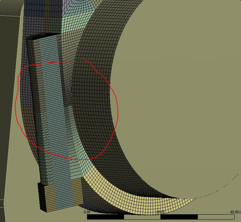 nn
January 1, 2021 at 4:03 pmSubscribernThe grid looks fine enough. If the purpose of the analysis is to simulate normal operation of the crank, you should not need plasticity.nOne thing I learned from your post is to try Flanagan-Belytschko for hourglass control. I didn't know about that when I posted in this discussion:n/forum/discussion/22403/can-anyone-help-me-to-do-explicit-dynamics-for-turning-operation/p1nWhat I noticed in that discussion is how the tool meshed with hex elements had horrible hourglassing,n
nn
January 1, 2021 at 4:03 pmSubscribernThe grid looks fine enough. If the purpose of the analysis is to simulate normal operation of the crank, you should not need plasticity.nOne thing I learned from your post is to try Flanagan-Belytschko for hourglass control. I didn't know about that when I posted in this discussion:n/forum/discussion/22403/can-anyone-help-me-to-do-explicit-dynamics-for-turning-operation/p1nWhat I noticed in that discussion is how the tool meshed with hex elements had horrible hourglassing,n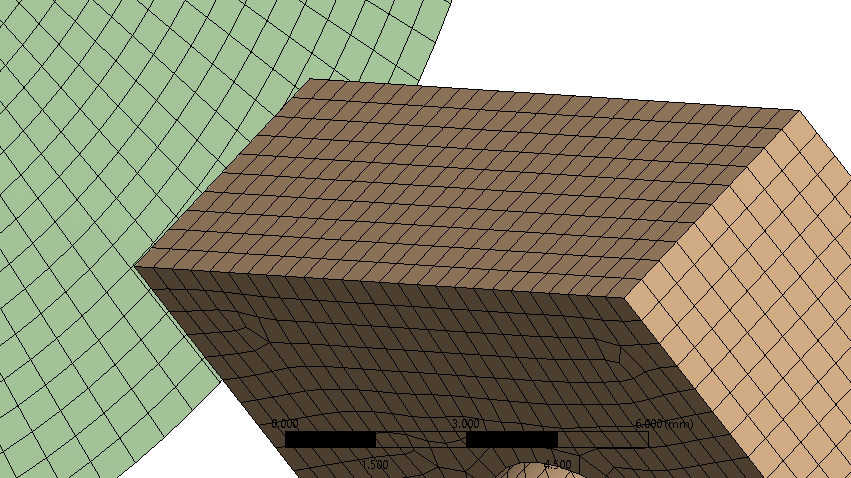
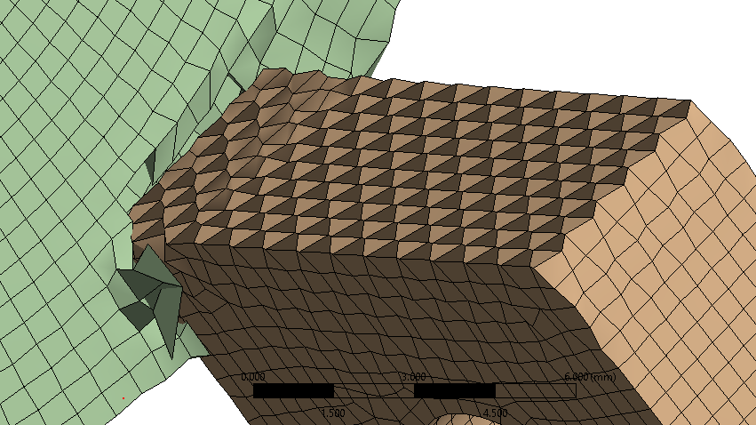 But when I remeshed with tet elements, that problem was resolved, at least in the tool.n
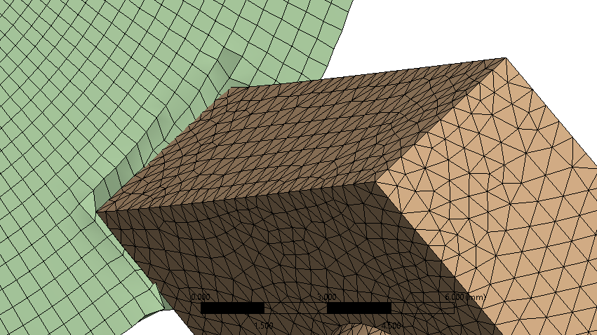 January 2, 2021 at 1:52 pmSubscriberYes, the purpose is just to evaluate if the design is safe. nAll the time, I was taught to use structural hexahedral grids for all explicit applications. I'll try using Tet elements in the hourglass-dominated regions. I'll let you know what happens.nI use the stiffness FB formulation for hourglass damping.nJanuary 2, 2021 at 8:41 pmSubscriberI remeshed the model with Tet elements. To my suprise, the miniumum quality improved from 0.30 to 0.36. There is no hourglass energy now. I was taught that tetra is a trash element and can be used only as a filler. Am I mistaken ?.Anyway, the problem of oscillatory motion persists. It appeared when I changed the Maximum Offset to 0.2mm in the two bonded contacts (threads), because some elements on the thread were not involved in the contact, they were not detected. This Maximum Offset seems to be essential for proper contact enforcement.nArrayI thought the problem could be due to the other frictional contacts, however everything looks fine there, friction coefficient set to 0.05.nBoth the piston head and the crankshaft move smoothly, without oscillating.nAny ideas?nJanuary 4, 2021 at 1:25 pmSubscribernPerhaps the initial conditions that came from Rigid Dynamics that originally produced a smooth motion of the connecting rod have been ignored/discarded after you made the offset change and the connecting rod starts the dynamic simulation with zero initial velocity. The instantaneous velocity of the crank bearing excites a lateral vibration of the connecting rod as it starts the motion from rest and not with a compatible initial velocity.nTry manually creating a rotational velocity about the piston bearing as an Initial Condition for the connecting rod.nJanuary 4, 2021 at 7:36 pmSubscriberArraynI took my time to (correctly I hope) initialise the case. Please take a look at that. These values were extracted from a Rigid Dynamics analysis, but that's the best we can do. The main coordinate system is placed in the same place and orientation in both RD and ED analyses.n

 We start the simulation while the piston head is in the Top Dead Centre. The crankshaft rotatates counterclockwise, as can be seen on the last screenshot.nnThe real question is: why it worked previously but now it doesn't? In both cases, the bonded contact glued the two interfaces together, the only difference was that previously the glue was not distribued along the whole circumference (theta direction) of the thread.nnI'd be grateful if you could take a look at my project and see what could've gone wrong. Please find it attached below.nArrayn
January 9, 2021 at 10:55 amSubscriberArray if you have any ideas, don't hesitate to share them with me nnI don't really know if there's any way of damping out this single frequency?n
We start the simulation while the piston head is in the Top Dead Centre. The crankshaft rotatates counterclockwise, as can be seen on the last screenshot.nnThe real question is: why it worked previously but now it doesn't? In both cases, the bonded contact glued the two interfaces together, the only difference was that previously the glue was not distribued along the whole circumference (theta direction) of the thread.nnI'd be grateful if you could take a look at my project and see what could've gone wrong. Please find it attached below.nArrayn
January 9, 2021 at 10:55 amSubscriberArray if you have any ideas, don't hesitate to share them with me nnI don't really know if there's any way of damping out this single frequency?n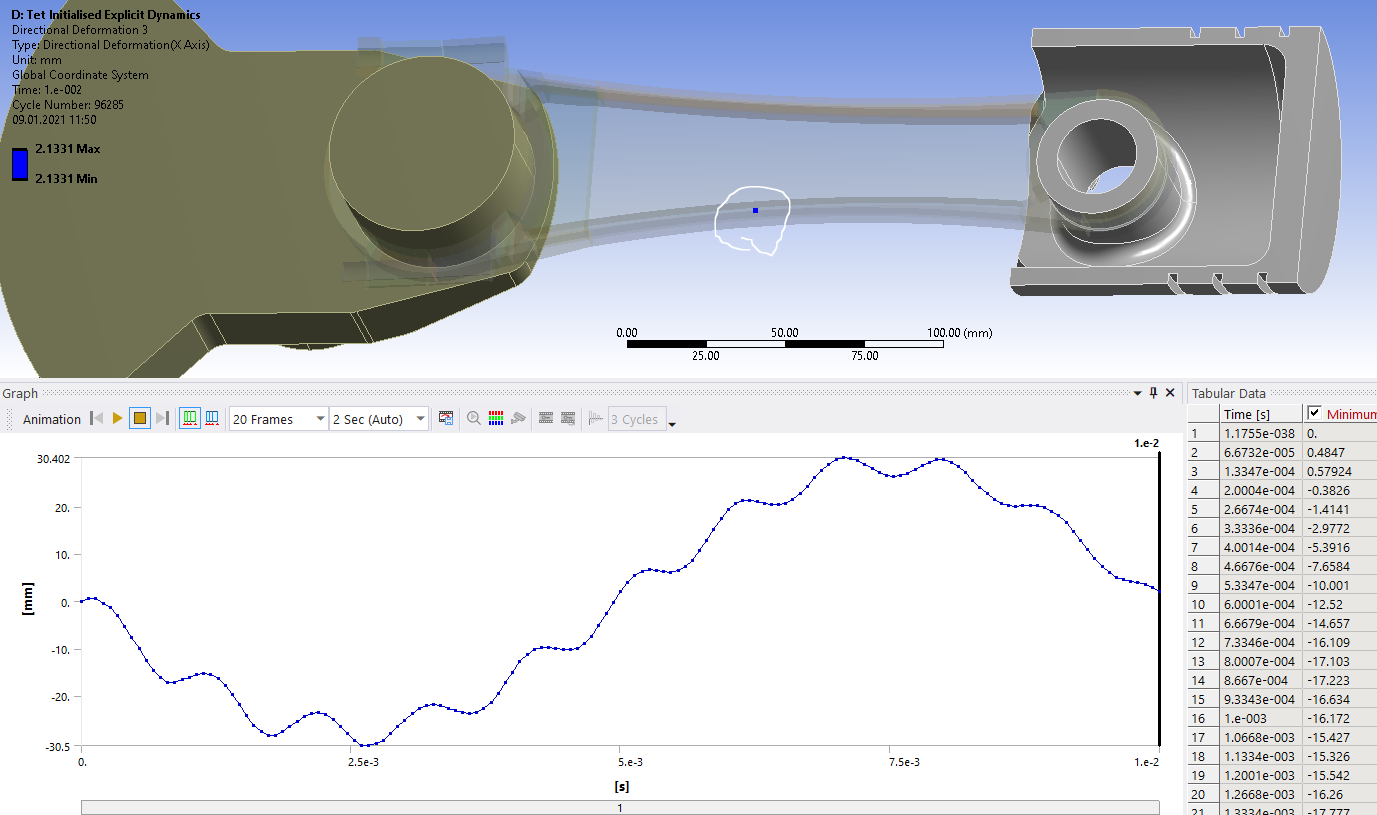 nIt's even more noticeable when the velocity is displayed.n
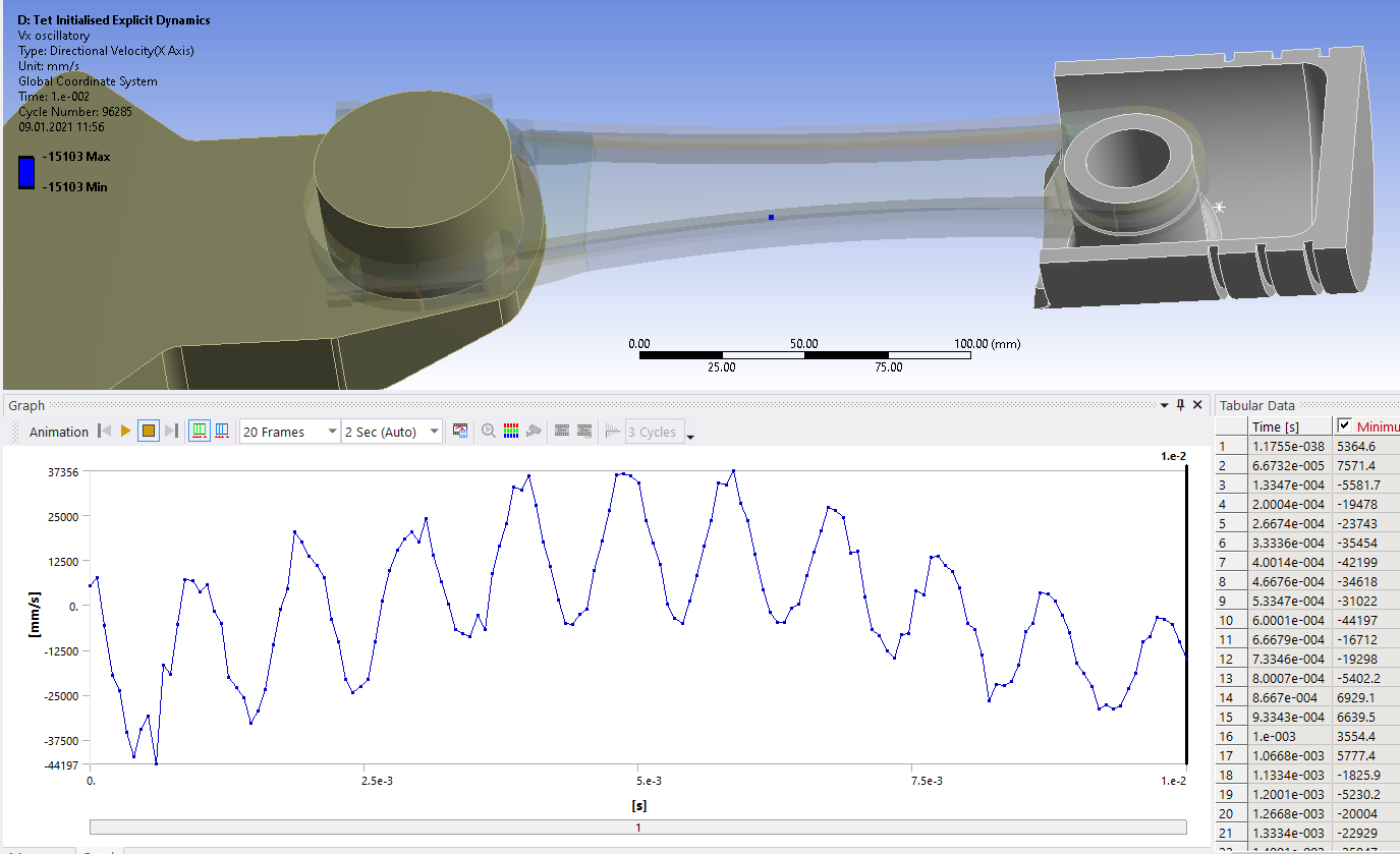 nn
Viewing 12 reply threads
nn
Viewing 12 reply threads- The topic ‘Energy error/hourglass error in a piston connecting rod crankshaft engine assembly Explicit Dynamics’ is closed to new replies.
Innovation Space Trending discussions
 Top Contributors
-
peteroznewman
 6465
6465 -
scabo
 1906
1906 -
Dennis Chen
 1458
1458 -
javat33489
 1308
1308 -
Shyam Prasad V Atri
1022
Top Rated Tags
© 2026 Copyright ANSYS, Inc. All rights reserved.
Ansys does not support the usage of unauthorized Ansys software. Please visit www.ansys.com to obtain an official distribution.
-


