-
-
February 15, 2018 at 7:13 pm
minko
SubscriberI need help with calculation of stand under scara robot. I think it should be a rigid dynamics but i´m not sure.Image is in attachment
-
February 16, 2018 at 2:45 pm
peteroznewman
SubscriberI don't see any file attached. You should also expand on the description of what results you want to get from your model of the robot simulation. Is it the deformations of the stand due to loads on the robot arm? That would not be Rigid Dynamics. Is it the forces and torques on the joints in the stand as the robot lifts a load? That would be Rigid Dynamics.
Â
-
February 16, 2018 at 7:06 pm
-
February 16, 2018 at 7:16 pm
peteroznewman
SubscriberOkay, I see your stand. What are the dimensions of the top and bottom plate? What is the plate thickness? What is the size of the hole in the plates? What is the dimension from the edge of the plate to the center of the hole? What is the tube diameter? What is the tube wall thickness? With all those numbers, you can easily draw the stand in SpaceClaim.
You also have to know the material, I assume it is steel, but what is the yield strength of the steel?
You also have to know the loads that the robot arm creates. There will be some force at some distance from the axis of the tube. You have to supply the magnitude and direction of the force and the distance from the axis and the top of the stand.
If you want to include the dynamic load, you will need the mass properties (mass and moments of inertia) of the entire robot arm including the 1 kg payload, and the acceleration of each joint.
-
February 16, 2018 at 7:39 pm
-
February 16, 2018 at 8:46 pm
peteroznewman
SubscriberOkay, I see the CAD file for the external features of the robot arm are available.
The robot has armA and armB and joint1and joint2. You need the mass properties of each arm individually as well as the mass of the base, and the peak angular acceleration of each joint in order to estimate the dynamic load on the stand.
-
February 16, 2018 at 10:19 pm
-
February 16, 2018 at 10:53 pm
peteroznewman
SubscriberThat last table may be sufficient to start a Topology Optimization on the Stand.
You can make load cases for the reaction torque and forces, you might also include a minimum natural frequency as well.
You need to decide on the fixed portion of the plate that bolts to the floor and the fixed portion of the plate that bolts to the base of the robot arm. The middle can then be free to be optimized. What height do you want the base above the floor?
-
February 17, 2018 at 10:27 am
minko
SubscriberBolts on the fixed portion of the plate to the floor will be M20 and dimensions of plate will be 350 x 350 x 30 mm. And bolts to the base of the robot arm will be M10 and dimensions of plate will be 200 x 200 x 25 mm .Base of robot from the floor will be 950 mm height.
So for summary I will do calculation in rigid dynamics, stand will be load with forces from the last table ? Then i will do topology optimalization and at finish I will do modal analysis? What with weight of robot arms i can´t find it?Â
-
February 17, 2018 at 1:28 pm
peteroznewman
SubscriberEpson has done the Rigid Body Dynamics for you when they provided the table of reaction forces and torques. That was a good find. Now you don't need mass and acceleration to calculate force and torque. You have been given the force and torque and will apply that to the model where the base bolts to the stand.
I created this before your reply with the dimensions, so if you need help, I can adjust it. The top of the model has a small raised section that matches the robot base and has the four bolt holes for the base. Then it becomes very wide to allow the Topology Optimizer to have a lot of material to work with. At the base, there is the floor plate. The robot base is not included in the geometry because that has more faces than the Student license allows, > 300 faces.
This model is not sufficient for a complete optimization, since I am only applying force and torque in one direction. It will optimize only for those loads. The model needs more static structural models with the force applied in four or more directions and the negative torque as well as the positive torque.
Modal Analysis is part of the optimization and the shape will be developed so that it does not vibrate below a minimum natural frequency. As I write this, I realize I should have added a concentrated mass of 29 kg above the top of the stand in the model. You need to estimate how high above the stand to put the point mass. Let me know if you need help with that.
-
February 17, 2018 at 2:39 pm
minko
SubscriberGreat thank you.
I´m not sure if I unersood right when you said that you had applied force and torque in one direction. You mean in one hole of the base or in one plane (for example XY) ? And how i should apply that in more directions. And you only apply mass point on the base of the stand? And with that estimate how high above the stand to put the point mass I really don´t know how to do it.
-
February 17, 2018 at 3:07 pm
peteroznewman
SubscriberI'm working on creating your dimension in 18.2 so within the hour I should have it done. You can show your appreciation by clicking Like on the posts that are helpful.
You might ask Epson if the Maximum Reaction Forces are calculated at the base mounting face and if the Maximum Reaction Torque is about a vertical axis only. If I raise the Reaction Force 500 mm above the base, I just created a Reaction Moment on the base. Do you know what I mean?
The forces and torques are all distributed to all four holes as you will see in the model soon.
You can take the entire 29 kg of the robot and divide it into three pieces, the base, armA and armB (or the head). Then use the side view drawings to estimate the height above the base plane for each mass. Then you could have three point masses, maybe even at different locations in space to use in the optimization.
-
February 17, 2018 at 3:21 pm
minko
SubscriberYes I now understand what you mean. I write them but I´m not sure if they respond.
You mean i need to find centre of gravity of each arm and give there mass point.Tthen i don´t need model of scara only 3 mass points.
-
February 17, 2018 at 3:42 pm
peteroznewman
SubscriberRight, you can have one point mass instead of three.
Here is the ANSYS 18.2 archive with your requested dimensions. The Static Structural has 6 load steps that apply the force in the +/- x/z directions and a +/- torque about the y axis. I also have a 29 kg point mass above the top of the stand.
I haven't run the topology optimization yet. I have to read the documentation to know that all six load steps are used in the optimization. I assume this is what it does.
Let me know if you have other questions.Â
-
February 17, 2018 at 3:56 pm
-
February 17, 2018 at 4:08 pm
peteroznewman
SubscriberStart ANSYS Workbench 18.2 from the Start Menu.
Then use File, Restore Archive and select the wbpz file that you downloaded.
Then it will ask you to Save As to save as a wbpj Workbench Project file and folder.
Once it is open, you have to Clear Generated Data on the Static Structural and Modal solutions before you run the Topo Opt.
Â
Just curious, what language is selected for your Windows?
Â
-
February 17, 2018 at 5:41 pm
minko
SubscriberNow it works thank you. I see that you made remote point 2 and you don´t use it? What with mass point, shoud I give it there?Â
I have in windows Slovak language I am from Slovakia in Europe.
Â
-
February 17, 2018 at 5:48 pm
peteroznewman
SubscriberThe first remote point is where the forces and torques are applied.
Remote point 2 is where the point mass is located, but attached to the same bolt holes.
Â
-
February 17, 2018 at 6:09 pm
minko
SubscriberAnd what with Maximal vertical reaction force 1500 N ? Are you sure of that force and moment aren´t be applyied at the same time?
-
February 17, 2018 at 6:24 pm
peteroznewman
SubscriberYou can add two more load cases for that. In Mechanical, on the Static Structural branch of the Outline, click on Analysis settings and change the number of steps from 6 to 8. Then on the Remote Force, type in 1500 in the Y column on row 7 and type in -1500 on row 8.
-
February 17, 2018 at 6:29 pm
minko
SubscriberAre you sure that vertical horizontal force and moment aren´t applyied simuntaneously and why?
-
February 17, 2018 at 9:03 pm
peteroznewman
SubscriberI'm learning Topology Optimization also, I'm just one model ahead of you, so I don't know the answer to your question. However, I want to learn how to perform a proper T.O. so I will be reading up about it. I don't know if an 8 step analysis creates 8 conditions for the optimizer to analyze or not, but I found I could not create multiple Static Structural blocks to feed into a single Topology Optimization system and I know that multiple load cases are required.
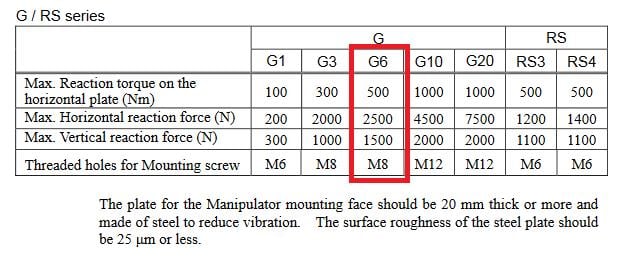
It is possible to combine multiple loads into a single step. A horizontal force, vertical force and moment can all be applied together, but there are two horizontal directions and the force and moments have to change sign, so what combinations will you use?
If the T.O. does use all 8 steps, there is a way to have the solution run faster. Since this is a linear system, after the first load step has solved, there is no need to invert the stiffness matrix again and again to compute the results for load steps 2-8. They can be calculated from the previous stiffness matrix. I can insert an APDL Command that tells ANSYS to reuse the previous stiffness matrix and I get the same results. I found the KUSE,1 command, in combination with choosing the Direct solver, can save 11 seconds on each solve which doesn't sound like a lot until you multiply it by 500 T.O. iterations and you just shaved 1.5 hours off the wait time.
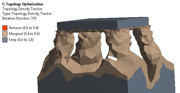
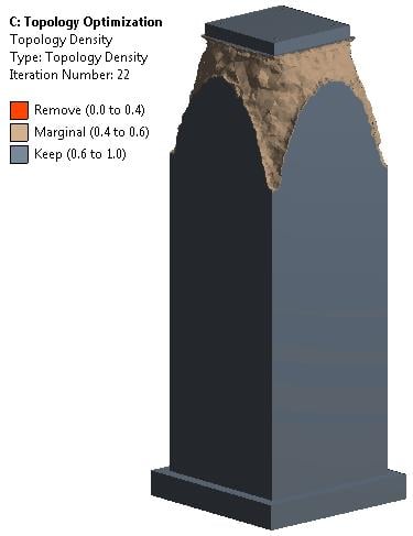
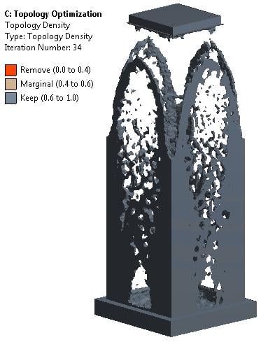
I will add those improvements to the next archive. Here is what the archive I attached above (6 steps, no vertical) does after 370 iterations on my 8 core computer. It hasn't converged, it's still calculating, but it looks like the mesh is a bit too coarse to give a nice surface. When more elements are used, the solve time will increase, so it will be even more valuable to reduce the solve time with KUSE and Direct.
-
February 17, 2018 at 10:17 pm
peteroznewman
SubscriberI found an answer about whether all 8 load steps will be used, look at the line objective 2. The answer is only load step 1.
Parameter setting:
     solver                  = Scpip
     ansys version           = 182
     design elements         = OptimizationRegionElements.dat
     feedersystem list:
      - Static system 'Static25' with id 25: 6 load case(s) at t = 1, 2, 3, 4, 5, 6
      - Modal system 'Modal35' with id 35: 1 mode(s) to find
     penalty parameter       = 3
     multiple eigenvalues tol = 0.1
     initial response scaling = yes
     minimum member size     = 0
     maximum member size     = 0
     minimum density         = 0.001
     maximum iteration       = 500
     acc                     = 0.001
     units                   = BIN
     output frequency        = 1
     max intermediate files  = 3
     objective 1             = single natural frequency 1 of feeder system 'Modal35' [1]
     objective 2             = single compliance (force load) for load step 1 of feeder system 'Static25' [1]
     constraint 1            = total mass with lower bound 50 and upper bound 50
     constraint 2            = natural frequency number 1 of feeder system 'Modal35' with lower bound 2000 and upper bound 1e+006
     method                  = SCP
     acc scp                 = 1e-006
     initial penalty scp     = 1
     asymptote strategy      = program controlled
I have figured out how to get all 6 load steps into the optimizer (vertical loads combined with moments).
-
February 18, 2018 at 3:44 am
peteroznewman
SubscriberI ran that model, and it converged. If I turn down the retained mass to 12%, the need for a minimum manufacturing constraint on member size is apparent. That will be added to the next run.
It was using all six load steps.
   objective 1       = single natural frequency 1 of feeder system 'Modal35' [1]
   objective 2       = single compliance (force load) for load step 1 of feeder system 'Static25' [1]
   objective 3       = single compliance (force load) for load step 2 of feeder system 'Static25' [1]
   objective 4       = single compliance (force load) for load step 3 of feeder system 'Static25' [1]
   objective 5       = single compliance (force load) for load step 4 of feeder system 'Static25' [1]
   objective 6       = single compliance (force load) for load step 5 of feeder system 'Static25' [1]
   objective 7       = single compliance (force load) for load step 6 of feeder system 'Static25' [1]
   constraint 1       = total mass with lower bound 50 and upper bound 50
Â
Â
-
February 18, 2018 at 10:23 am
minko
SubscriberGood work thank you I try to solve it
Just for interest who are you when you have too much time for solving these problems and you respons to all questions?
-
- The topic ‘Dynamics robot (scara) simulation’ is closed to new replies.
-
5879
-
1906
-
1420
-
1306
-
1021
© 2026 Copyright ANSYS, Inc. All rights reserved.


