TAGGED: fluent, lift, mrf, rotor, spaceclaim
-
-
September 23, 2024 at 7:37 pm
Osama Maddani
Subscriberhello
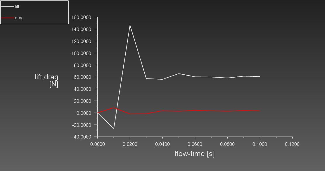
Im trying to simulate a drone as a school project, the issue is im getting zero lift force.
to my understanding is that the thrust should only be applied byt the quadcopter's rotors and not through the velocity inlet.
I have tried steady state with angular velocity given the rotor's walls, and I have tried MRF using rotating mesh, at an rpm of 10000.
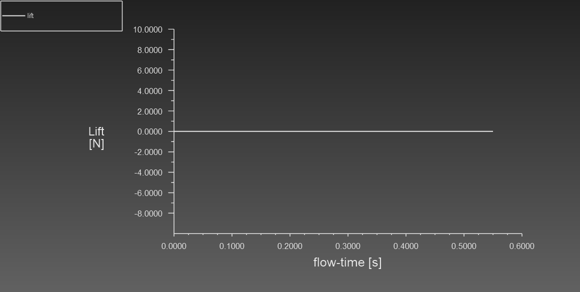
the report definition measuring the forces on the walls.
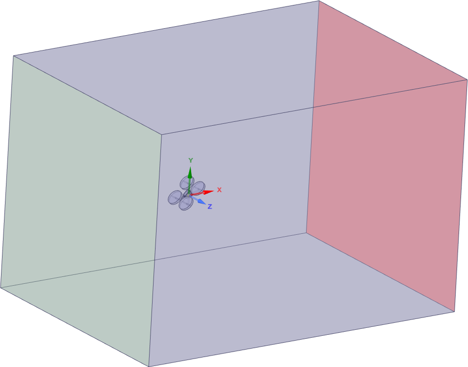
the drone is inclined forwards with a pitch of 30 degress
velocity inlet at the front with speed = 0, or pressure outlet it gave the same result.
rear face of the domain is a pressure outlet
all the walls around the exterior of the domain aside from these two are symmetry.
I am stuck as I dont know what else am I missing.
using my sense the rotor's rotation should be enough to provide measurable thrust to move the drone upwards and forwards.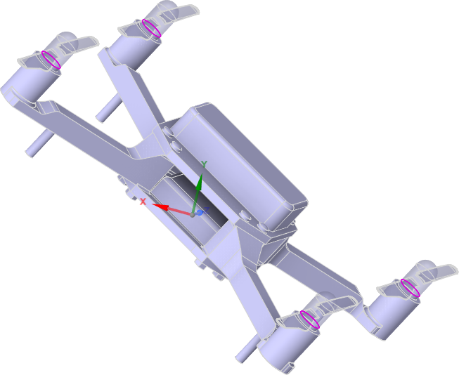
-
September 23, 2024 at 8:50 pm
Osama Maddani
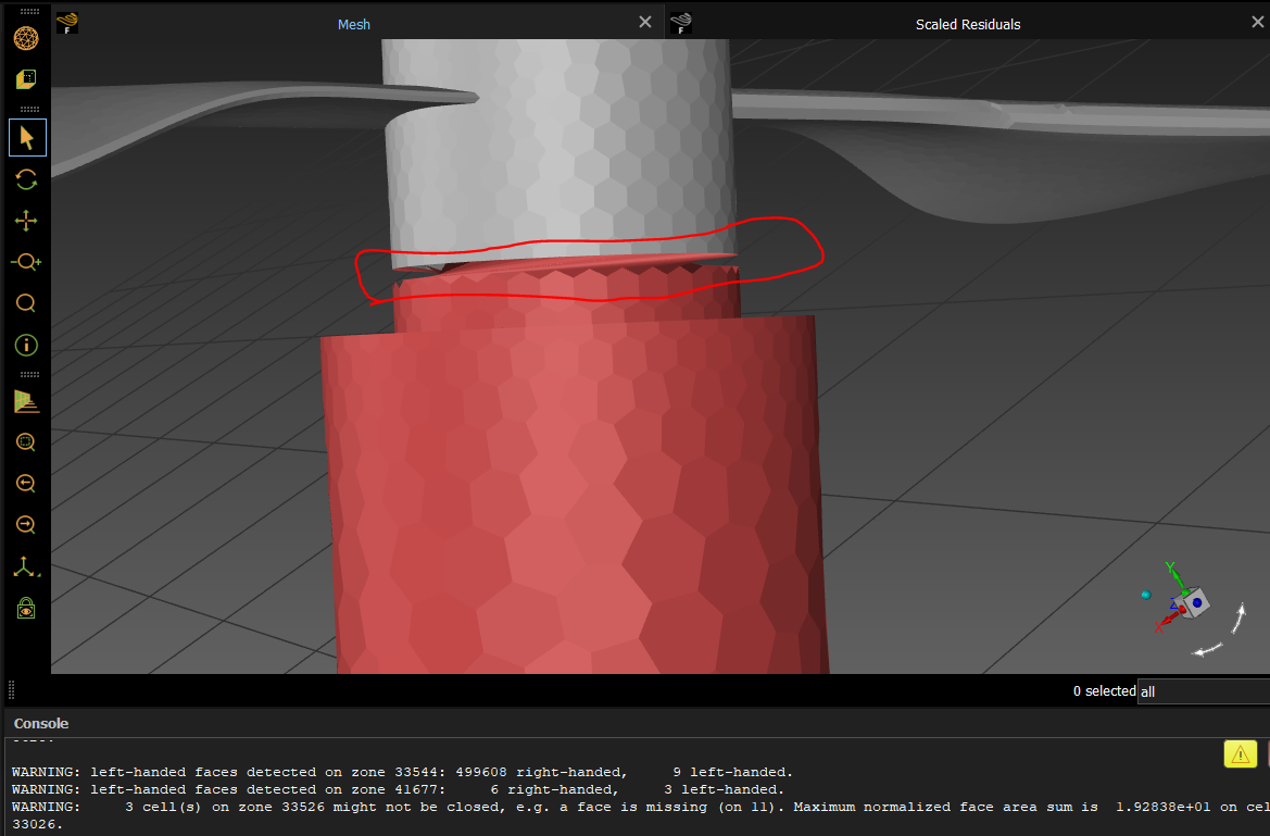
SubscriberI changed the rotors and now I am getting this wierd error after trying to run a transient simulation,
4901 cells with non-positive volume detected.
even though the minimum mesh orthogonal quality is above 0.2 -
September 23, 2024 at 9:30 pm
Osama Maddani
Subscriberok now the second issue was solved by writing the cse, and relaunching Fluent again, but the problem is now I am getting floating point exception error, even though in the motion preview the movement works ok as expected, the mesh quality is ok.
-
September 23, 2024 at 9:32 pm
-
September 24, 2024 at 8:42 am
Rob
Forum ModeratorMRF can't corrupt the mesh as nothing is actually moving. If you have sliding mesh (mesh motion) you need to ensure the rotor & part of the shaft are completely disconnected from the adjacent domain. The common boundary will be an interface pair.
Looking at the geometry I'd also remove some of the unnecessary details as they're costing you mesh count for no real benefit.
-
September 24, 2024 at 9:02 am
Osama Maddani
Subscriberok, no what I did was pitch it at 45 degrees forward so that the axis of rotation vector is now (x,y,z) (1,-1,0), apparently the mesh problem has happened due to the 30 degrees vector number being not precise enough to ensure perfect mesh rotation, not sure but this is my speculation.
so this solves the second part of the problem for now, though I used (internal) boundary condition not (interface), is that a problem?
secondly what could be wrong with the lift being zero (or very close to it ) from the report definitions.
I am now running the case with the 45 degrees pitch and will see how it goes.
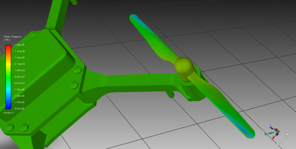
this is it currently running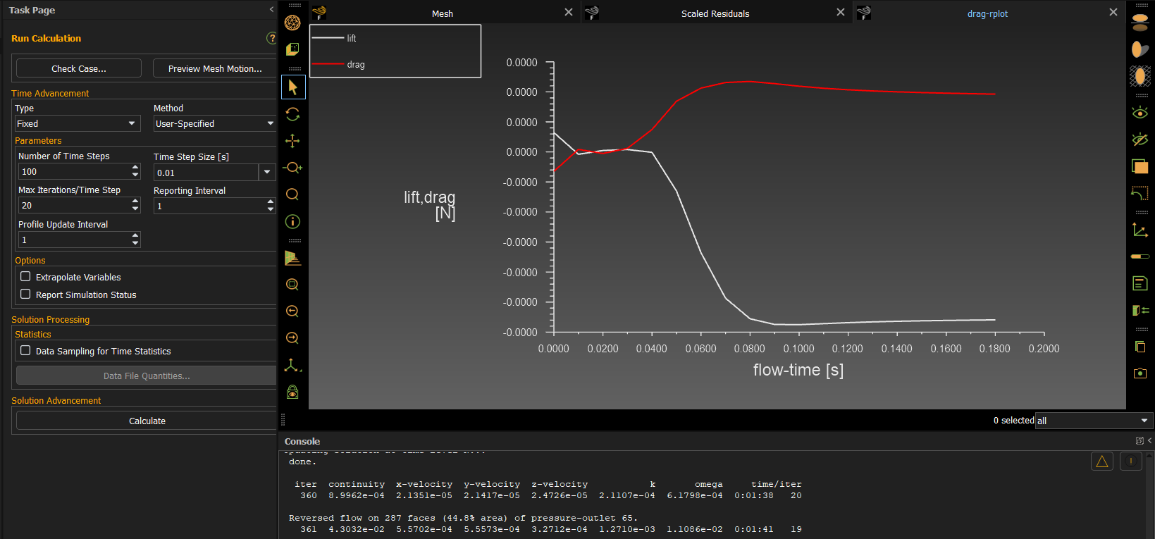
-
September 24, 2024 at 9:05 am
Osama Maddani
Subscriber-
September 24, 2024 at 9:52 am
-
-
-
September 24, 2024 at 10:26 am
Rob
Forum ModeratorAgain, with mrf (reference) frame the mesh doesn't move so can't become twisted. That would typically have an interior zone between it and the outer domain. So not sure what's happened. With mrf if you're not quite there with the vector it'll just give some slightly odd rotation effects in the velocity field.
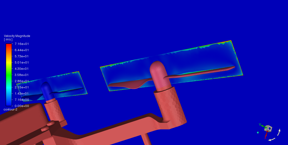
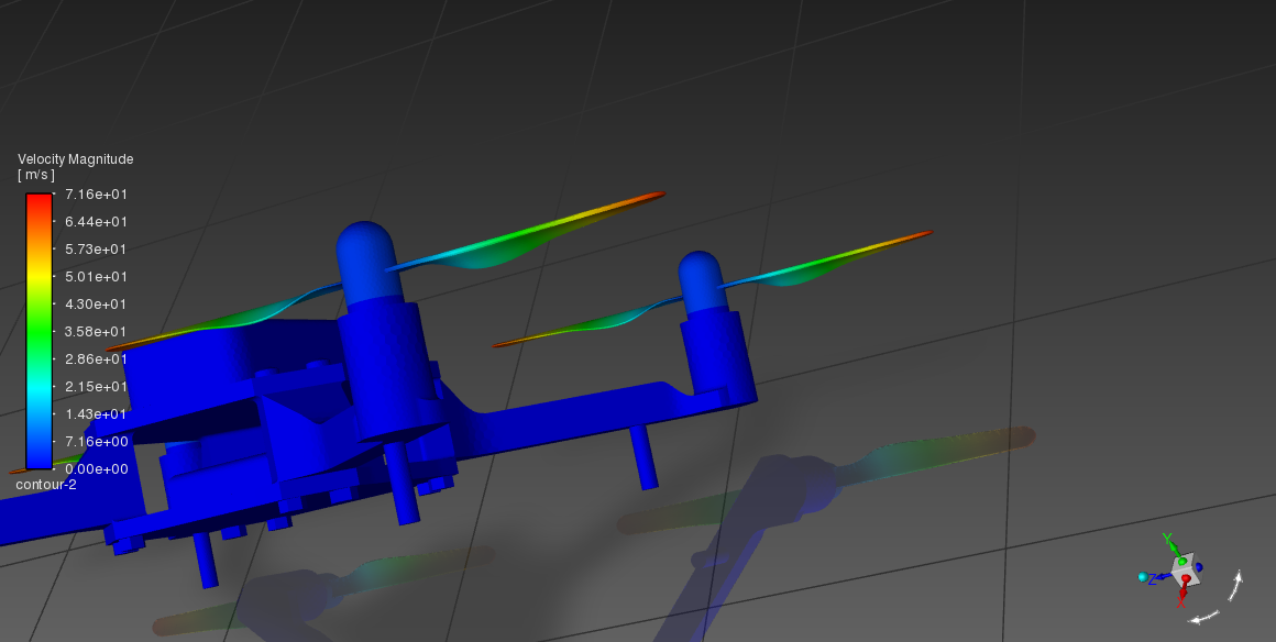
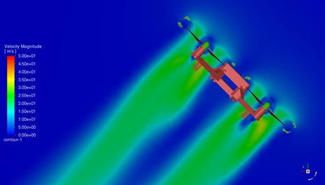
I'd expect some value of lift/drag regardless as it's near impossible to not see a number. If you report the value from the panel rather than plotting is it still precisely zero? If you put a contour through the rotor plane (vertical) how does the velocity field look?
-
September 24, 2024 at 10:42 am
-
-
September 24, 2024 at 12:14 pm
Rob
Forum ModeratorHmm, why is there no flow from the impellors onto the plane surfaces?
-
September 24, 2024 at 3:03 pm
-
September 24, 2024 at 3:21 pm
Rob
Forum ModeratorOK, now there's a number you need to review the force and also reference area: read the lift/drag definitions.
-
September 24, 2024 at 6:08 pm
-
September 24, 2024 at 7:57 pm
-
September 25, 2024 at 8:55 am
Rob
Forum ModeratorClick "per zone" on the report panel as the drone body won't help the sums. With mrf can you run steady? You've done about 10 time steps to get to 0.1s so I'm a little concerned that it's a settled result. You also have a spinning blade that's not just generating force in the y-axis.
-
October 9, 2024 at 3:51 pm
Osama Maddani
SubscriberHello , after many days I have solved the problems
the solution is two fold, first the domain interfaces have to be assigned as "internal" BCs when meshing in fluent then later assigned as interfaces, it doesnt works if they were walls with share topology or interface from meshing for some reason.
the second thing is changing the rotor speed from 10k rpm which is what I was using to 50k rpm genrated approximatly 13.5N of lift and -13.5N of drag (negative drag is forwards thrust), forwards and upwards forces are almost identical because the drone is pitched forwards at 45 degress,which is logical since a 200mm*200mm drone with 130mm rotors weighs between 300-700 grams, then the lift is sufficient.
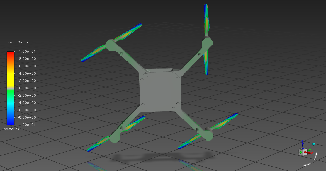
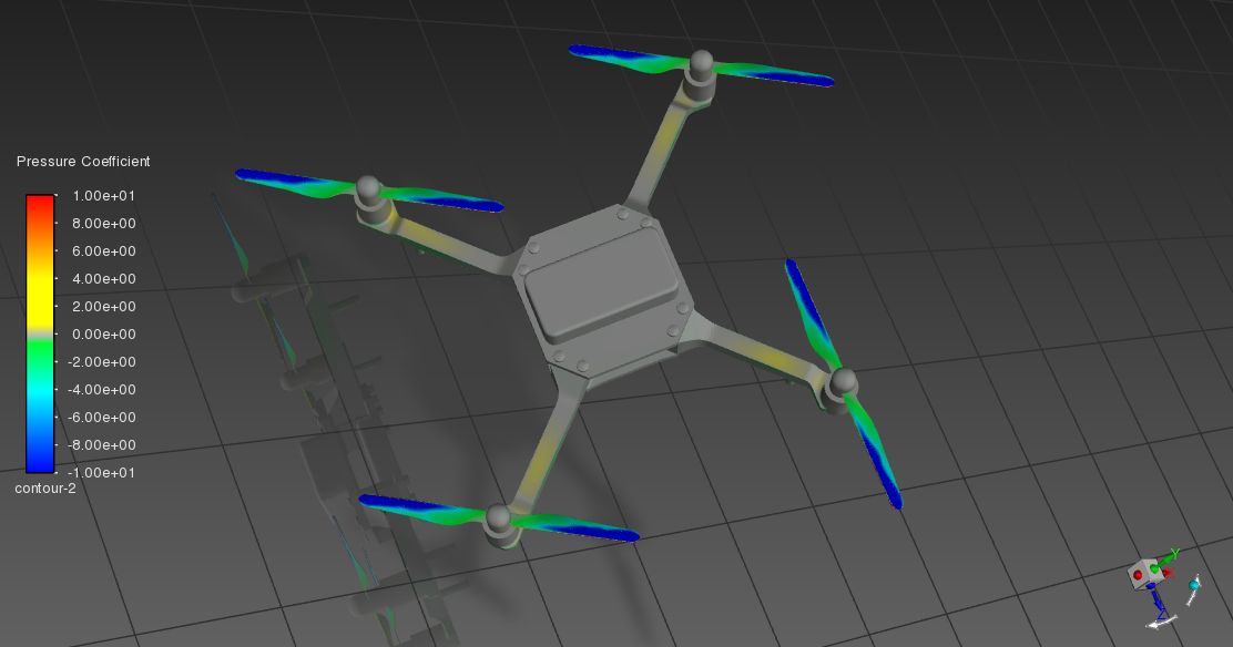
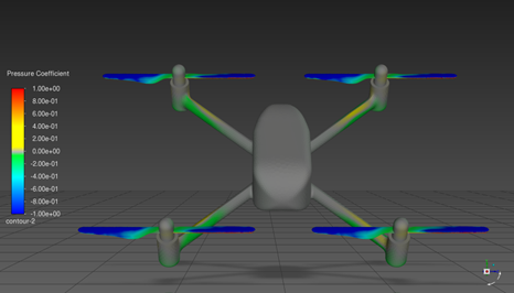
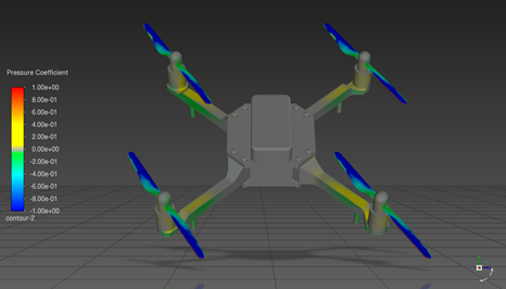
I already knew that "per zone" force prints the force on each component, in my case the walls: (drone, fl rotor, fr rotor, rl rotor, and rr rotor), even though that wasnt the solution to my low lift problem it was the low rpm, that report has shed light onto a very important observation for the report which is the drone body force acts against the rotors' force, so drone body has negative lift and positive drag, which is the next step of my study of streamlining the drone's body so it can produce more lift and less drag so the pverall thrust is more due to changing the shape of the body from that exposed shape in the above photos that represents a DIY kit sort of drone to a streamlined body that is more representative of a body that can be made using 3D printing or an injection molding from an off the shelf product.
the problem is considered solved.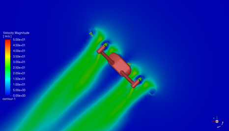
-
-
- You must be logged in to reply to this topic.


-
3427
-
1057
-
1051
-
896
-
887

© 2025 Copyright ANSYS, Inc. All rights reserved.

