Ansys Assistant will be unavailable on the Learning Forum starting January 30. An upgraded version is coming soon. We apologize for any inconvenience and appreciate your patience. Stay tuned for updates.
Fluids

Fluids

Topics related to Fluent, CFX, Turbogrid and more.

DPM modelling

    • Milhm
      Subscriber
      Hi,nwhat is the best value for number of tries in discrete random walk model when simulating steady state injection?n
    • Rob
      Forum Moderator
      The purpose of the option is to allow the parcels to disperse due to turbulence. If you have a large number of parcels from the injection then fewer tries may be needed, if you have few parcels from the injection then you need more tries. There is also an upper limit on the number of tries based on your hardware. Somewhere between 1 and 1000 is fairly common, 10-100 may be a good starting point. n
    • Milhm
      Subscriber
      i have 200 number of streams and my droplets have constant diameter of 20 micron.Which number of tries is good for it?n
    • Rob
      Forum Moderator
      How big is the domain, are particles passing through or are you seeing incomplete tracks? n
    • Milhm
      Subscriber
      domain is a pipe with diameter of 260mm and lenght of 4 m.particles are sprayed into the pipe.nno i do not see incomplete tracks. n
    • Rob
      Forum Moderator
      In which case keep increasing the number of tries until whatever you're monitoring stops changing or the computer falls over. Save before plotting particle trajectories! My earlier comment about 10-100 tries being a good starting point stands. n
    • Milhm
      Subscriber
      trajectories in steady injection should be arranged and regular or Irregular and disordered?nare these trajectories acceptable?.
    • Rob
      Forum Moderator
      The particles will follow the flow to varying levels depending on diameter and relative material density. The result looks like what I'd expect to see from a DPM track, whether they're correct is for you to judge based on the flow. n
    • Milhm
      Subscriber
      the main flow is air and droplets are water.ni have another question.What are good values for step length factor and length scale?nhow they should be selected for a simulation?n
    • Rob
      Forum Moderator
      Default aren't bad, otherwise it's a trade off between speed and accuracy. Use the automatic accuracy controls in the numerics too: that tends to reduce the cpu wastage where particles aren't changing direction or speed very quickly. n
    • Milhm
      Subscriber
      ok i will enable automatic accuracy controls.nso far i enter 0.001 for length scale.is it logical and correct?ni have another question.in steady injection, residuals become periodic due to dpm iteration interval.is it correct?n nn
    • Rob
      Forum Moderator
      The value isn't nonsensical, but read the documentation to see what it means. Several values we use as defaults are numerically sensible rather than being correct for a particular case. nYes, the residuals will spike with every DPM update as the source terms are updated. n
    • Milhm
      Subscriber
      ok.nwhat is the logical value for dpm iteration interval?I use 200 so the residual plot become horizontal in each interval.should i increase this value?n
    • Rob
      Forum Moderator
      On each DPM update Fluent re-calculates the particle trajectory and hence source terms (how much the particle alters the flow). If the update is very frequent the solution may never converge, and may use a lot of cpu resource, on the other hand the solver is using the correct DPM data. If the interval is very long, you'll see spikes, use less cpu but risk using less up to date data. Both high and low intervals are valid depending on how much of a change you see in the particle tracks and how much cpu you have. Default is 10, and 10-50 is a common range, I often use the default. n
    • Milhm
      Subscriber
      in my simulation,when i use steady injection,particle tracks rotate and sweep.nand when i use unsteady injection, their distribution becomes disordered.n and leed to wrong contours.in your opinion where is the problem?n
    • Milhm
      Subscriber
      in my simulation,when i use steady injection,particle tracks rotate and sweep.nand when i use unsteady injection, their distribution becomes disordered.nnand leed to wrong contours.in your opinion where is the problem?n
    • Milhm
      Subscriber
      in my simulation,when i use steady injection,particle tracks rotate and sweep.nand when i use unsteady injection, their distribution becomes disordered.nnand leed to wrong contours.in your opinion where is the problem?.
    • Rob
      Forum Moderator
      Looks about the same to me. In steady tracking you see a solid track that is the trajectory. In transient you see the location of each parcel in the domain. So, in the first image you see lines, in the second a cloud of spheres, joining the spheres up based on their injection facet will produce the line you see. n
    • Milhm
      Subscriber
      i mean there is a problem here.because they should be distributed with symmetry but they are distributed inordered.they should be distributed in any cross section with symmetry.where is the problem?n
    • Rob
      Forum Moderator
      What is the inlet condition? And which way is up?n
    • Milhm
      Subscriber
      inlet condition is mass flow inlet.nwhat do you mean by which way is up?n
    • YasserSelima
      Subscriber
      which way is upstream n
    • Milhm
      Subscriber
      the particles go along the downstream direction(positive Y axis) toward outlet.n
    • Milhm
      Subscriber
      the particles go along the downstream direction(positive Y axis) toward outlet.nn
    • Milhm
      Subscriber
      i should say something.i run these simulations in parallel.Can parallel processing affect particle tracking?n
    • Milhm
      Subscriber
      the particles go along the downstream direction(positive Y axis) toward outlet.n
    • Milhm
      Subscriber
      could it be due to injection velocity?i used 100 m/s for injection velocityn
    • Rob
      Forum Moderator
      If the injection velocity matches the gas then nothing odd will happen, if you've mixed the x, y & z up then it's anybody's guess where they'll go! By up is gravity turned on.
    • Milhm
      Subscriber
      gravity is not included.ni know they go up but they do not follow a straight line through outlet and they rotate.nhere in this image i increase number of streams to 600.particles still go out of their straight way.nn
    • Rob
      Forum Moderator
      Can you post the injection set up and similarly the inlet condition panel? n
    • Milhm
      Subscriber
      the problem is an L shaped pipe.material is air.it is assumed as real gas.inlet boundary condition is mass flow inlet. and outlet is pressure outlet.nsomewhere near outlet injection is done.nnn
    • Rob
      Forum Moderator
      If the flow is in the y direction why is the injection in the x direction? n
    • Milhm
      Subscriber
      it is injected through center of pipen
    • Rob
      Forum Moderator
      At 90 degrees to the direction of flown
    • Milhm
      Subscriber
      yesn
    • Rob
      Forum Moderator
      And you expect the droplets to go straight towards the axis and then be deflected by the main flow? Now you explain the set up, I take it you have 3-4 injections each doing this? n
    • Milhm
      Subscriber
      i have four injection which are placed radially.ni expect droplets go in a straight way through outlet without rotation of particle tracks about axis.i expect something like this imagenn
    • Milhm
      Subscriber
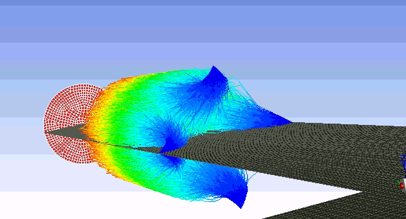
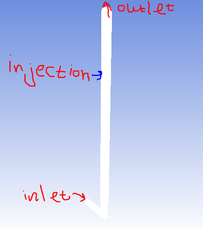
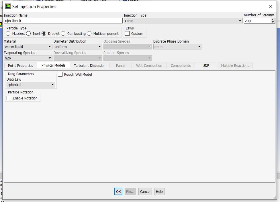
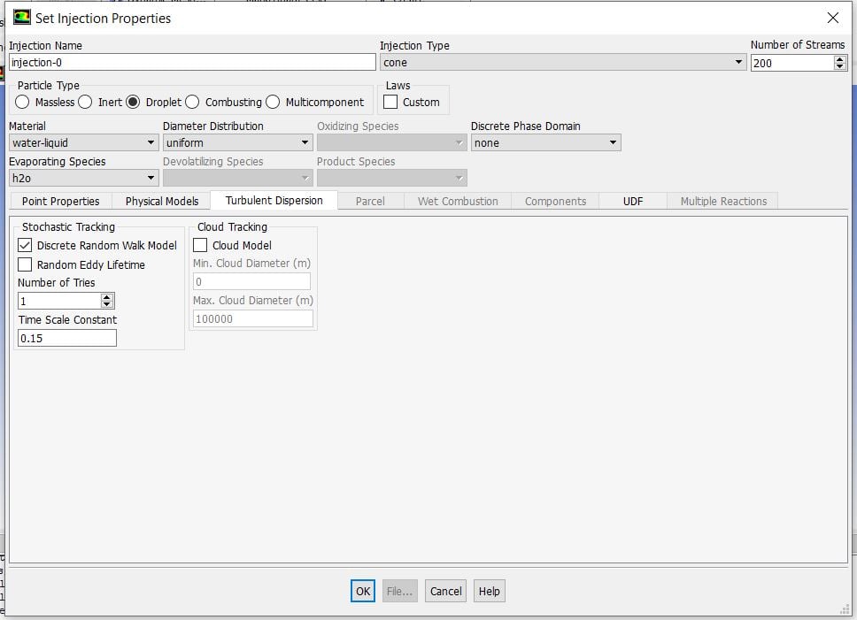
      this is vector plots of main flow in different cross sections.as can be seen from the image,main flow is rotating.Can it cause particles to rotate?n
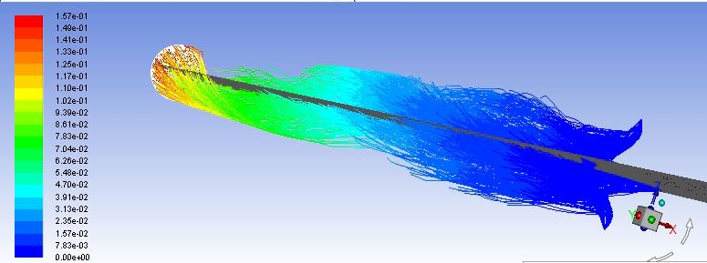
nmain flow has mass flow rate of 1.1 kg/s and temperature of 600 k.it is solved as a compressible flow.operating pressure is 101325.gauge pressure in pressure outlet boundary conditions is set as 0.nafter flow is solved,ndensity is about 0.57,ninlet velocity is about 60 m/s,nin the elbow velocity is about 110 m/s,nbig part of domain has velocity of about 50 m/s,nmach number is between 0.004 to 0.25.nare they correct and logical?n
    • Rob
      Forum Moderator
      The injections will flow as per the vector you initially set. Any slight distortion in the flow or mesh will tend to trigger a very slight eccentricity, this then cascades to generate small amounts of swirl. Have a look at the pitchfork bifurcation phenomena. In your case the inlet being off axis may be be enough to trigger the effect. n
    • Milhm
      Subscriber
      main flow has mass flow rate of 1.1 kg/s and temperature of 600 k.it is solved as a compressible flow.operating pressure is 101325.gauge pressure in pressure outlet boundary conditions is set as 0.nafter flow is solved,ndensity is about 0.57,ninlet velocity is about 60 m/s,nin the elbow velocity is about 110 m/s,nbig part of domain has velocity of about 50 m/s,nmach number is between 0.004 to 0.25.nare they correct and logical?nn
    • Milhm
      Subscriber
      main flow has mass flow rate of 1.1 kg/s and temperature of 600 k.it is solved as a compressible flow.operating pressure is 101325.gauge pressure in pressure outlet boundary conditions is set as 0.nafter flow is solved,ndensity is about 0.57,ninlet velocity is about 60 m/s,nin the elbow velocity is about 110 m/s,nbig part of domain has velocity of about 50 m/s,nmach number is between 0.004 to 0.25.nare they correct and logical?.n
    • Rob
      Forum Moderator
      I don't know, are they? You have the boundary conditions, the domain size and some knowledge of the flow field prior to building the model. Those values are all within a range I'd expect to see in a CFD model, as are 400m/s and 60 bar. n
    • Milhm
      Subscriber
      for example is the density logical?nwhat do you mean by 400m/s and 60 bar?n
    • Milhm
      Subscriber
      for example is the density logical?nwhat do you mean by 400m/s and 60 bar?n
    • Milhm
      Subscriber
      for example is the density logical?nwhat do you mean by 400m/s and 60 bar?n
Viewing 44 reply threads
  • The topic ‘DPM modelling’ is closed to new replies.
[bingo_chatbox]