-
-
December 23, 2024 at 1:55 amH1640846343Subscriber
When transmitting through a long distance curved waveguide, the transmission of light in the middle is almost zero, so I want to scan the radius of the curved waveguide to find the most suitable parameters. Since I divide the bent waveguide into inner radius and outer radius, with a waveguide width of 0.5um, I am not sure if my operation of scanning both inner and outer radii simultaneously is correct during scanning, and if I can obtain the desired result by setting the result as the transmittance T of a power monitor?
-
December 23, 2024 at 2:05 amH1640846343Subscriber
-
December 23, 2024 at 3:08 pmKirillAnsys Employee
Dear Subscriber,
Here are a few observations based on the screenshots you’ve shared:
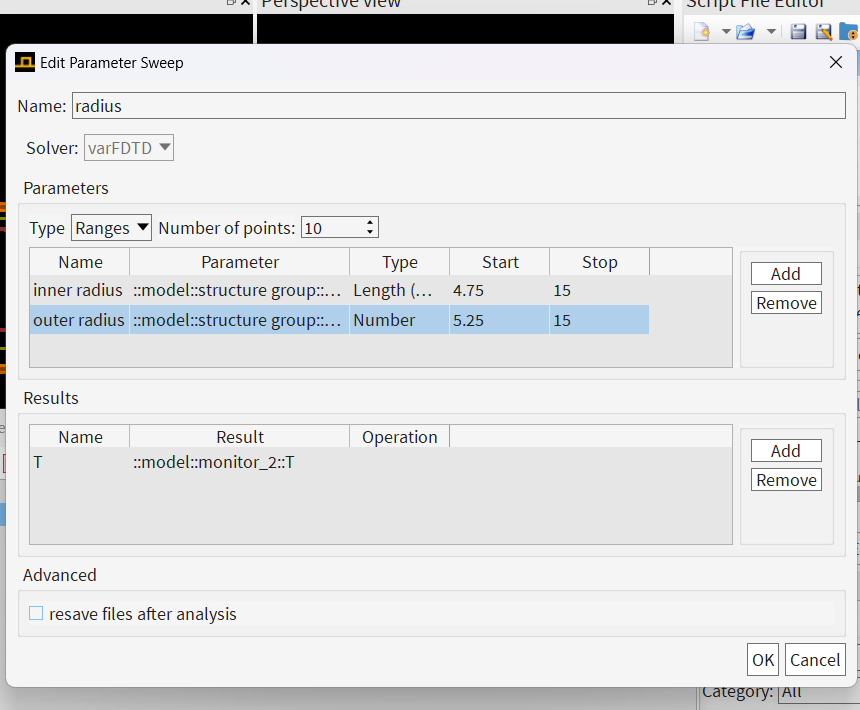
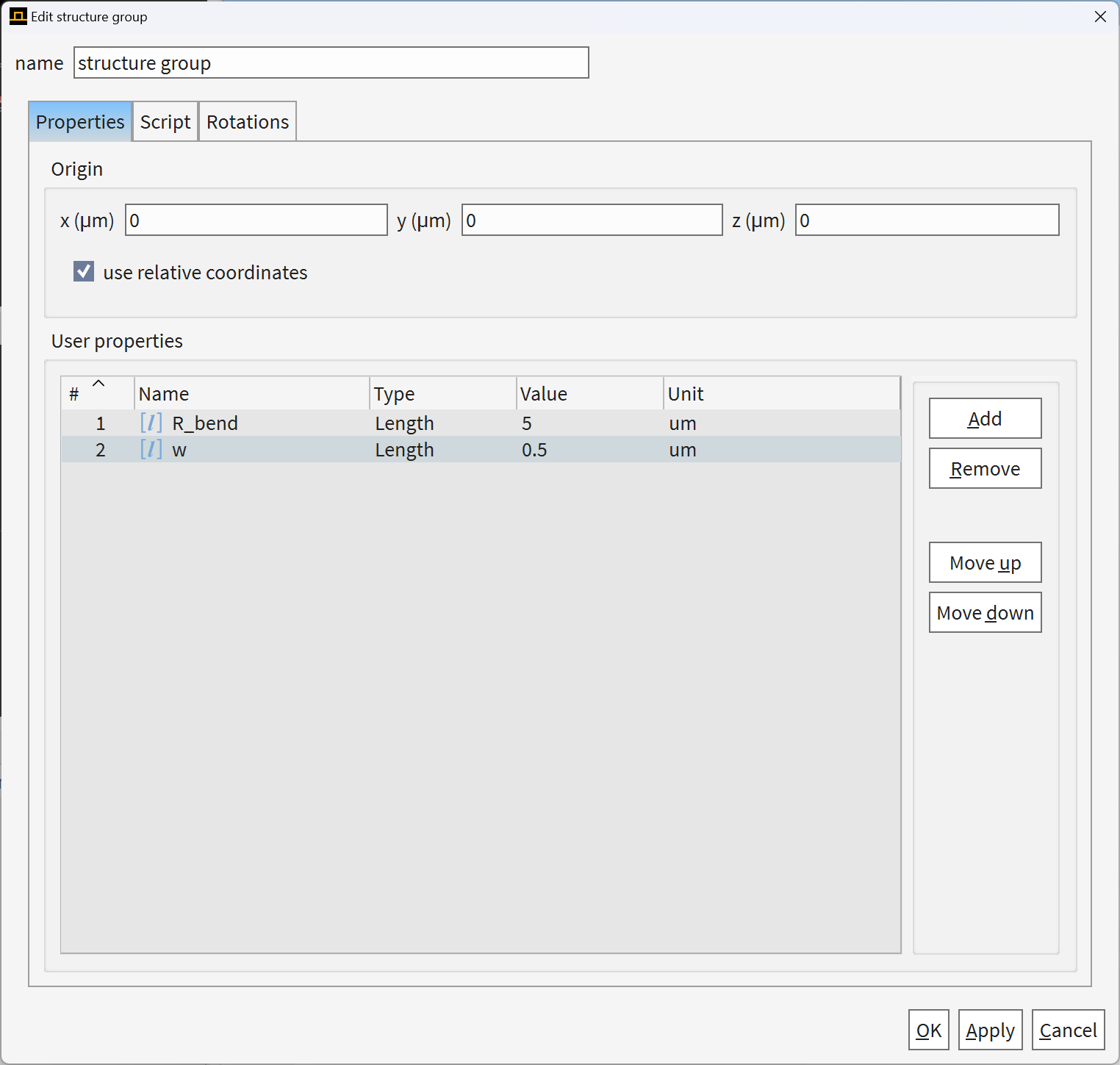
When setting up the sweep, your parameters have different types. Please check if this reflects the actual geometry you are interested in. Based on the naming, it seems both parameters are intended to represent lengths. While this is not necessarily a mistake and depends on your script, it is a good practice to keep parameter types consistent.
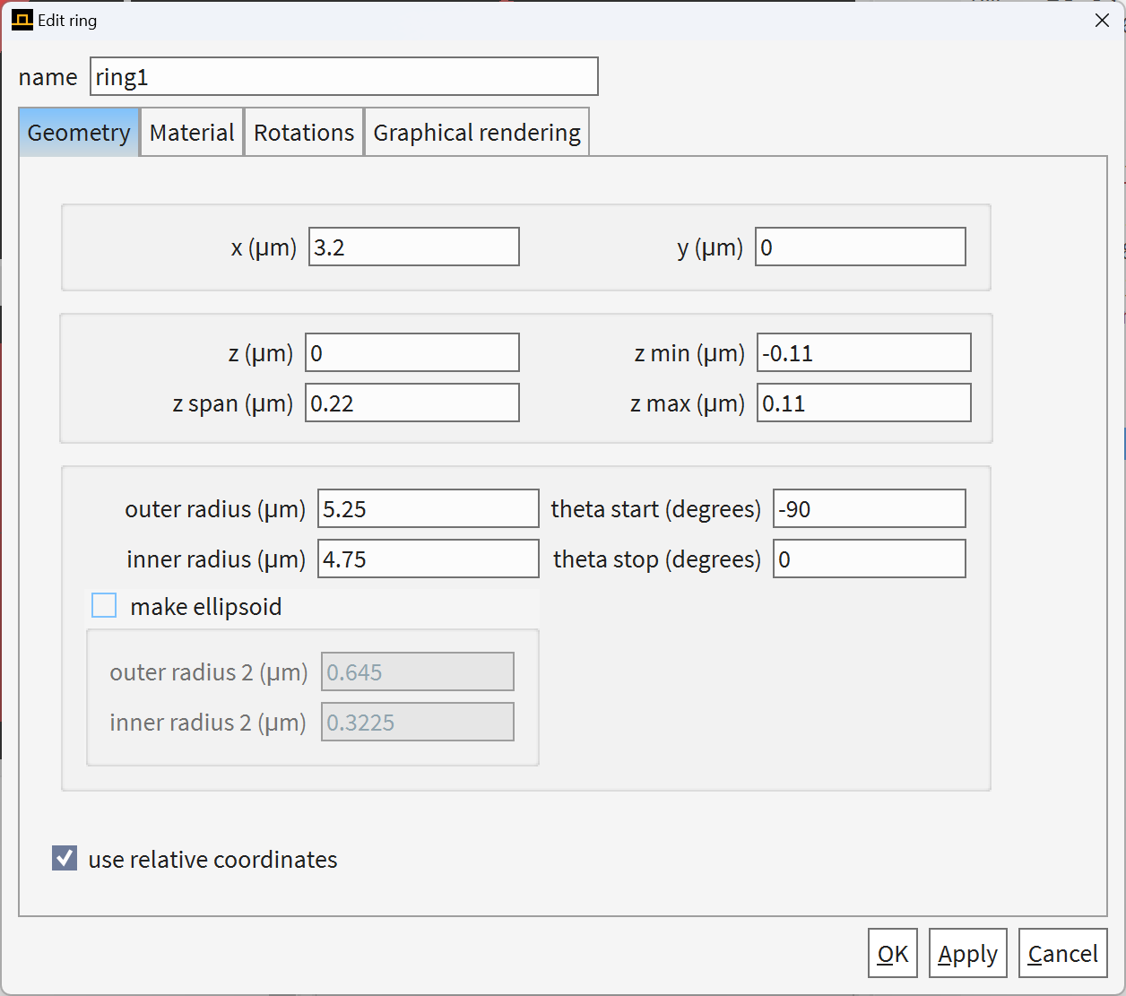
With your current sweep settings, you have 10 iterations starting from:
- Inner radius = 4.75 [some length units], outer radius = 5.25, ...
to - Inner radius = 15 [some length units], outer radius = 15.
Please double-check if this was your intention.
- Inner radius = 4.75 [some length units], outer radius = 5.25, ...
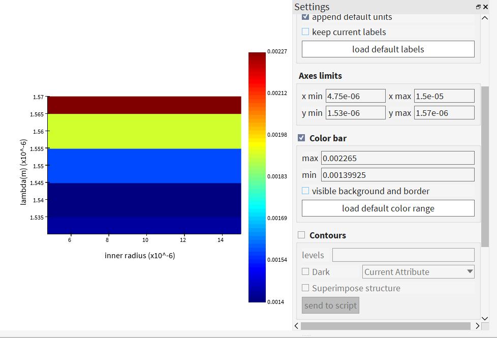
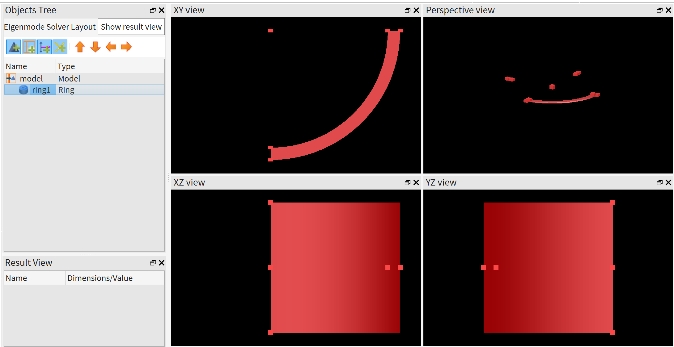
Regarding your plot: What you are seeing appears to be a colormap of your function ─ probably transmittance ─ versus inner radius and wavelength, which varies with wavelength (vertically).
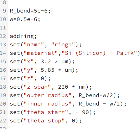
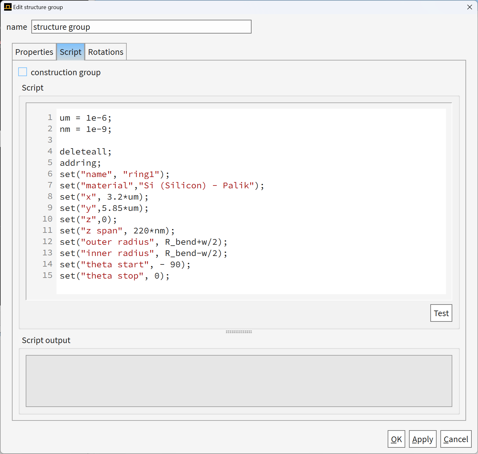
As a suggestion, here’s an approach you might consider: If you want to vary both radii simultaneously, modify your script to define a single radius R to describe the waveguide. Then, set: inner_R=R−ΔR, outer_R=R+ΔR. Next, sweep R over the desired range.
Best regards,
Kirill -
December 24, 2024 at 2:37 amH1640846343Subscriber
Thank you for your reply.
I tried to set R, but I couldn't modify the parameter names for the inner and outer radius, otherwise it would report an error, which puzzled me. This resulted in me still being able to only find the inner radius and outer radius during the parameter scanning process, which did not achieve the desired effect of scanning through only one parameter R. I think there must be something wrong with me, and I hope you can help me solve it. -
December 26, 2024 at 9:01 pmKirillAnsys Employee
Dear Subscriber,
The script you provided works fine and generates the following ring segment object.Â
Make sure you create a Structure Groups - Simulation object, define your parameters in Properties tab, and use this script under Script tab.
Best regards,
Kirill
-
- You must be logged in to reply to this topic.
- Difference between answers in version 2024 and 2017 lumerical mode solution
- Errors Running Ring Modulator Example on Cluster
- Import material .txt file with script
- Trapezoidal ring
- Help for qINTERCONNECT
- Absorption cross-section of AuNR excited by prism-based TIR
- Issues with getting result from interconnent analysis script
- Topology Optimization Error
- How to measure transmission coefficients on a given plane .
- Edge Coupler EME Example Issue
-
1602
-
602
-
599
-
591
-
366
© 2025 Copyright ANSYS, Inc. All rights reserved.