TAGGED: ansys-mechanical, cardiovascular_stent, displacement
-
-
July 29, 2023 at 9:45 am
Arash Kavosi
Subscriber -
July 29, 2023 at 10:53 am
peteroznewman
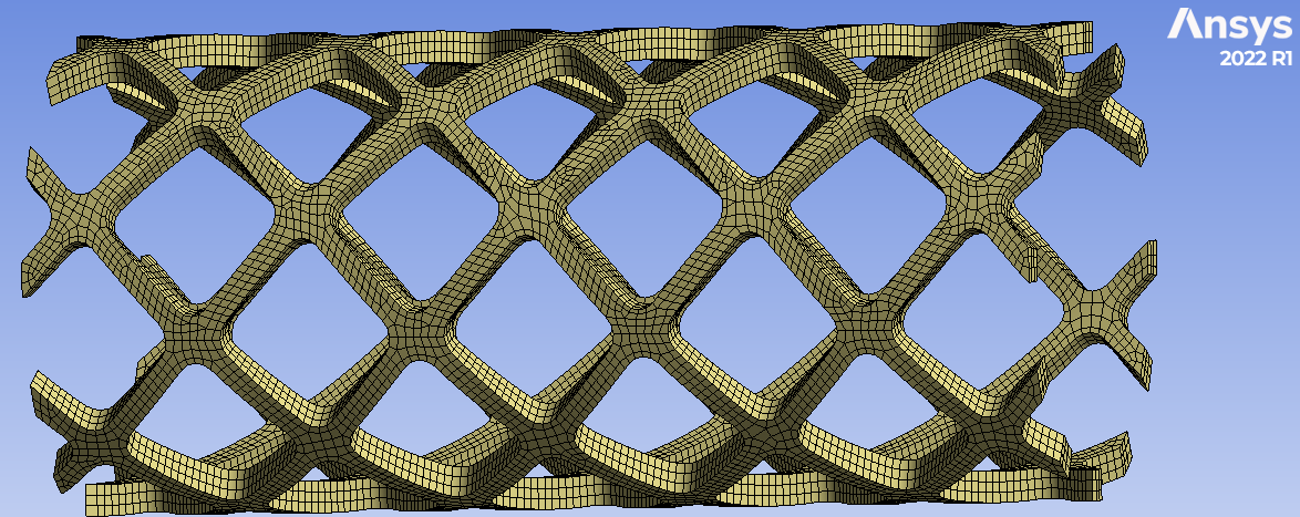
SubscriberI see the stent axis is along the global Y axis. Create a Cylindrical coordinate system at the center of the stent with the Z axis along the global Y axis.
Pick 3 vertices at the center of the stent, spread around the diameter and apply a Displacement support. Change the Coordinate System to be Cylindrical. Set the Displacement to be Y (tangential) and Z (axial) to 0 and leave X (radial) Free.
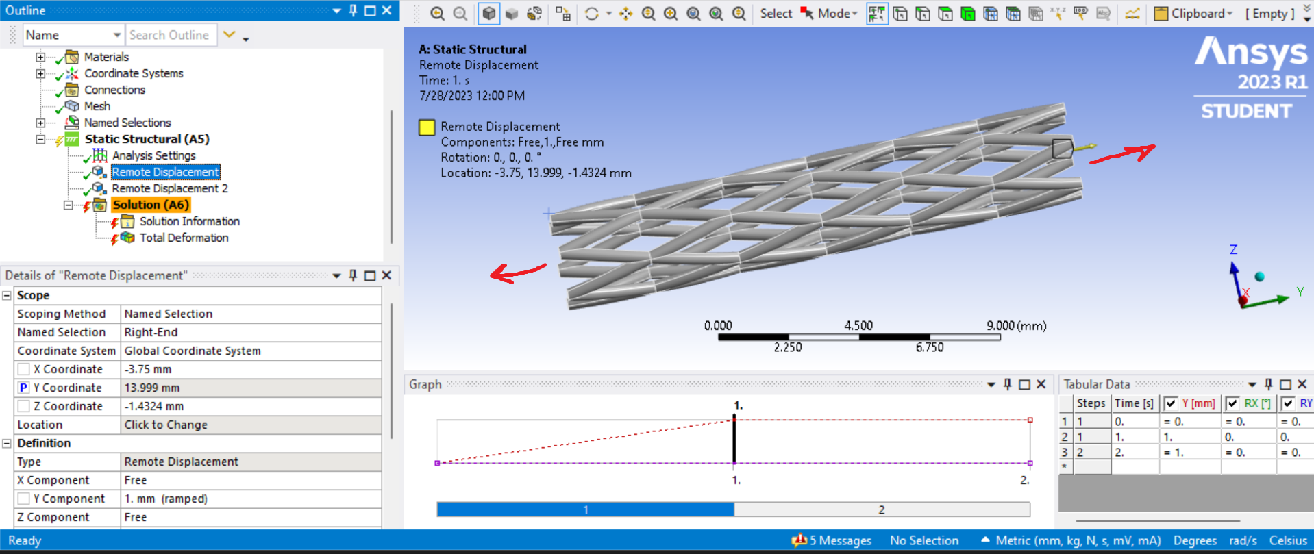
Select all the faces at the +Y end of the stent and apply a Remote Displacement, behavior = Deformable, to move the faces using a value in the Y component only and leave all others Free. Repeat with another Remote Displacement at the -Y end of the stent with a negative number in the Y component.
You may get a "not enough constraints" warning, which you can ignore, but you should not get an error.
-
August 3, 2023 at 8:54 am
Arash Kavosi
SubscriberHI and Thank you for your help
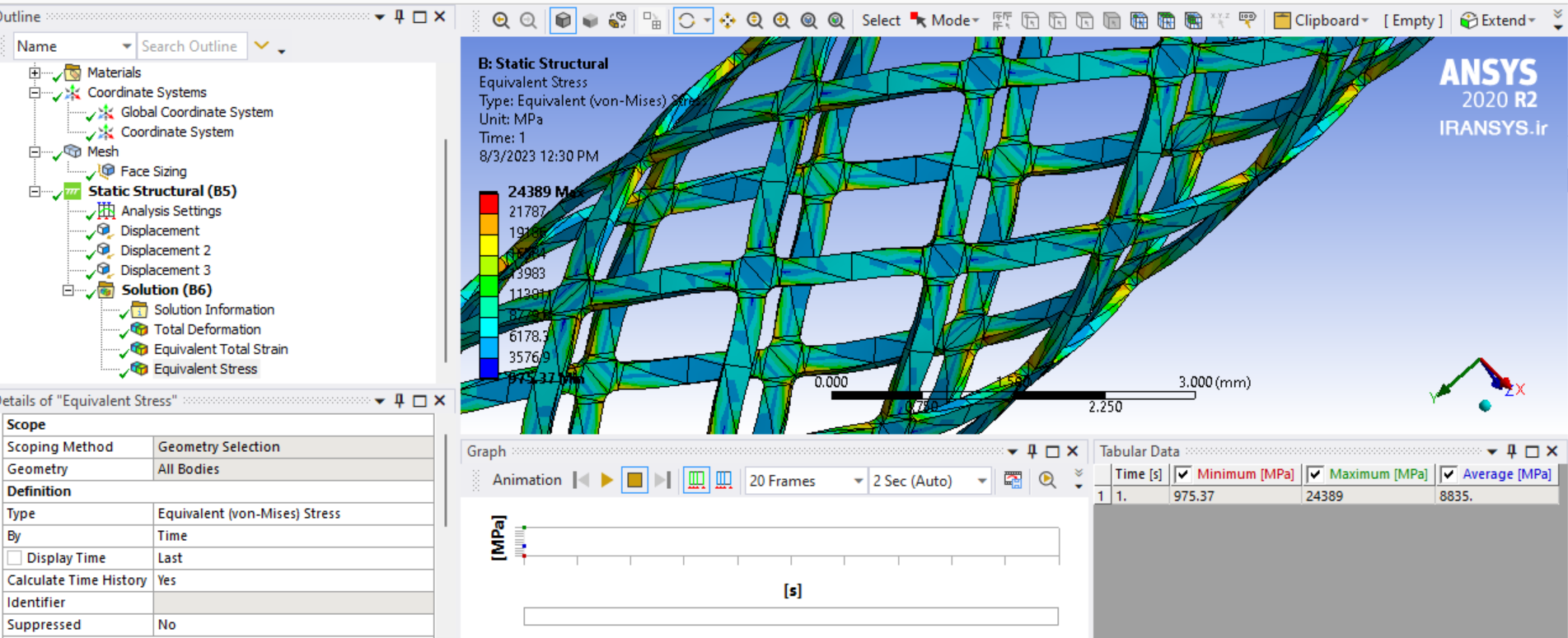
I designed my stent with Diameter=4mm, Length=10mm, and Thickness=0.1mm. two displacement on ends each one 1mm. the material is selected Structural Steel.
my problem is, the maximum stress is very high! 11080MPa. how I can modify it?
Even I made the corners Filleted at solidworks but didnt change in Stress.
Also, at che chart Stress-Strain, for every displacement values the diagram is linear. but its not supposed to be!
can you help me please?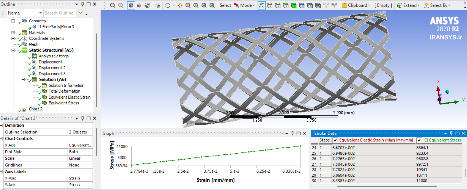
-
-
July 29, 2023 at 6:45 pm
Arash Kavosi
Subscriber -
August 3, 2023 at 3:15 pm
peteroznewman
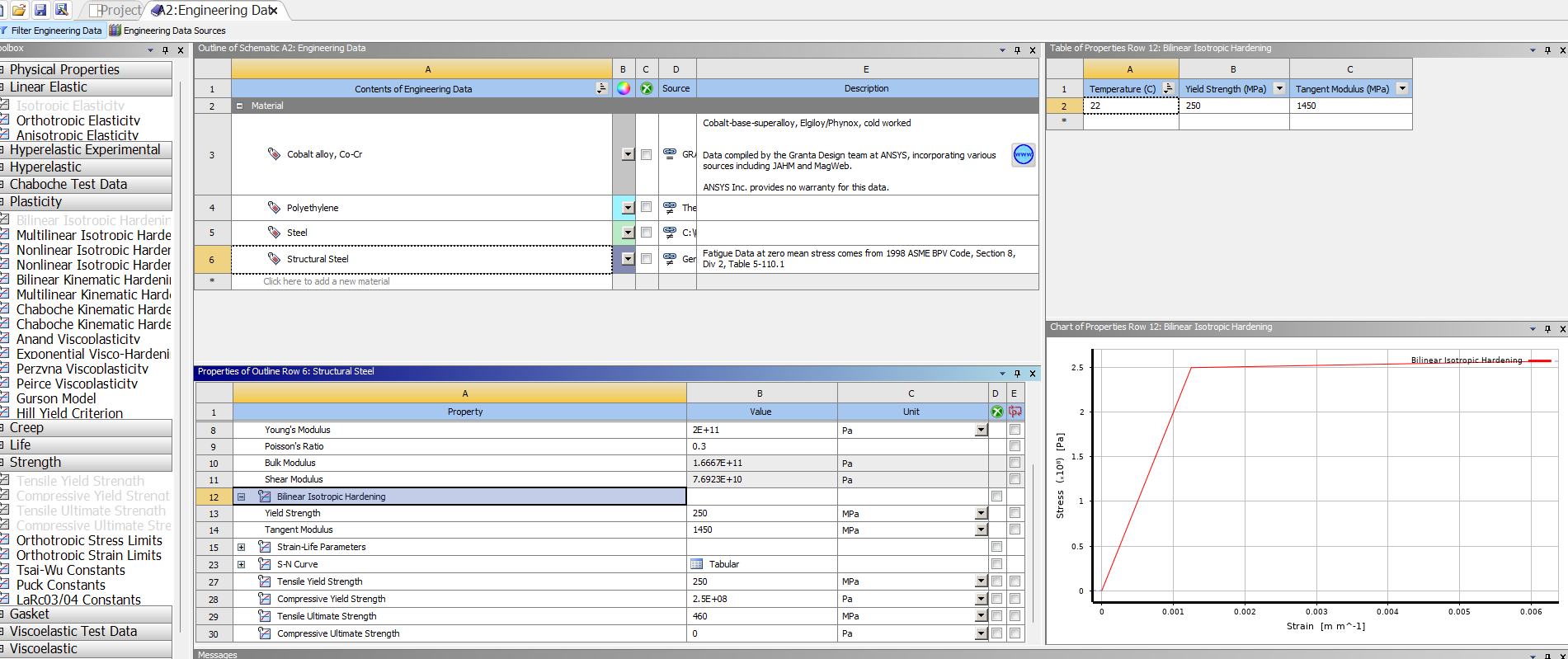
SubscriberThe material must have a plasticity material model to cause plastic strain to develop and reduce the stress from getting too high.
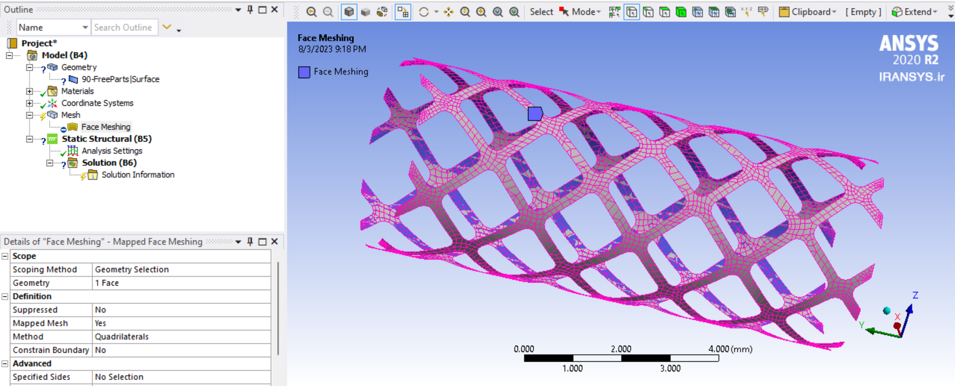
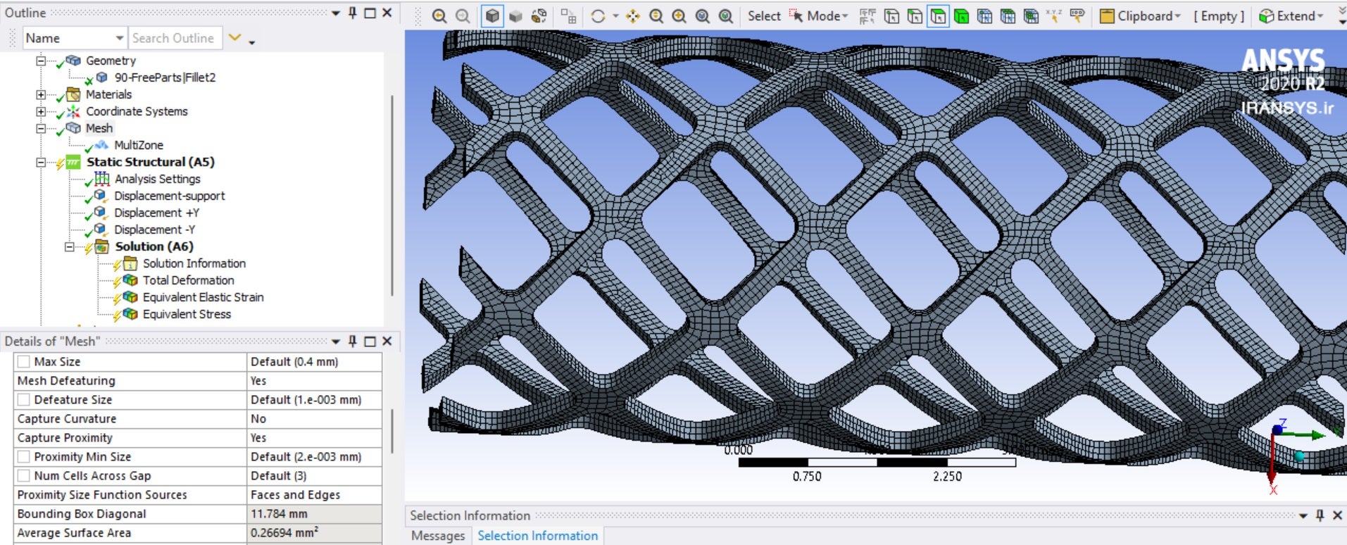
To support a plasticity material model, the mesh should have 3 linear elements in each direction in the thin sections. That means 3 elements across the width and 3 elements through the thickness. One way to achieve that is to use the Mesh Pull feature. That requires you to go into SpaceClaim, select the inner face of the solid and use Copy/Paste to create a surface. Then delete the solid. In Mechanical, mesh that surface with Quad elements, and Pull those elements into Hex elements.
-
August 3, 2023 at 8:22 pm
-
August 3, 2023 at 10:42 pm
peteroznewman
SubscriberUnfortunately, the Pull mesh command was introduced in 2022 and is not in the 2020 release.
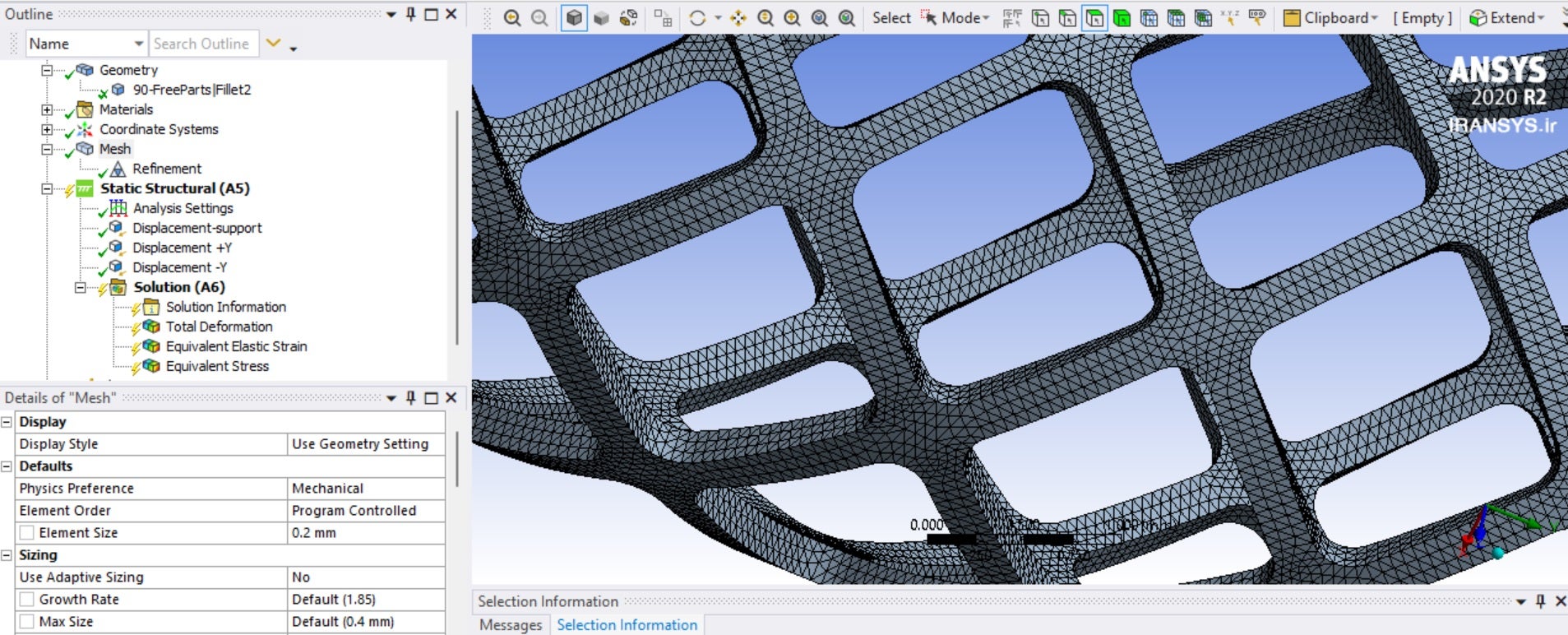
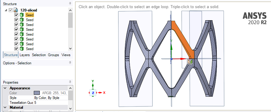
You will have to use the solid body and slice the solid up to make it simpler to mesh. Slice the stent so every straight segment is separated from the intersection solid. These can all be meshed with a Sweep Method where you sweep through the thickness with 3 elements. Use Default Element Size so that there are 3 elements across the width of each straight face. In the image you show above, there are only 1 or 2 elements across the width.
-
August 4, 2023 at 10:45 am
-
-
August 4, 2023 at 7:54 am
Arash Kavosi
Subscriberunfortunately I searched and couldnt find any instructions. can you guide me for this approach? you mean that the problem of high stress is because of the type of the meshing?
-
August 4, 2023 at 10:48 am
peteroznewman
SubscriberWhat is the yield strength of the stent material?
-
August 4, 2023 at 12:13 pm
Arash Kavosi
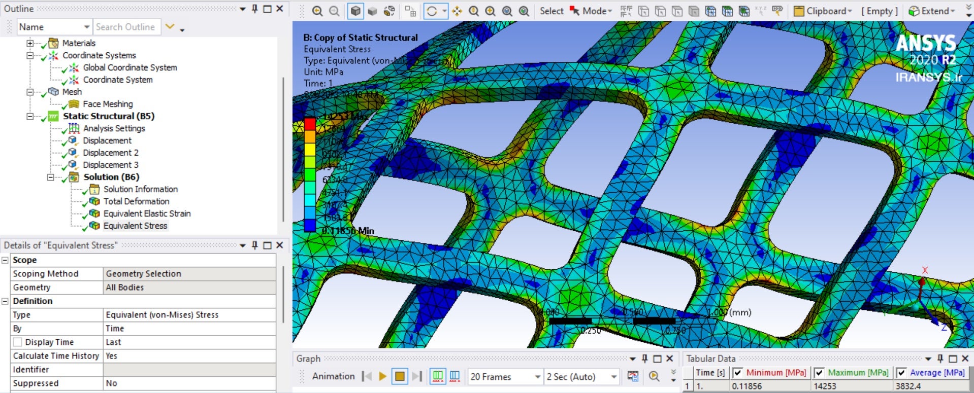
SubscriberI tried for Structural Steel (Yield =470MPa), stress becomes 30000MPa
Also I tried for CO-Cr (Yield=1400 MPA), stress becomes 2300MPa
by reducing the size of the meshing, stress increases!
-
-
August 4, 2023 at 12:40 pm
peteroznewman
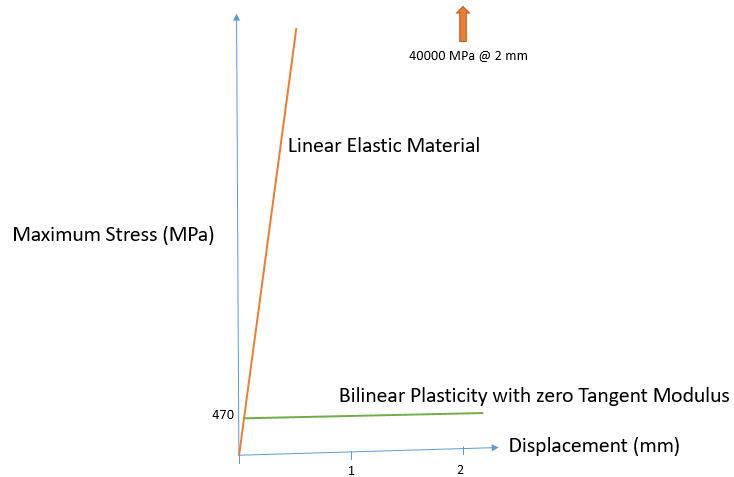
SubscriberOpen the Structural Steel in Engineering Data. In the toolbox, drag and drop the Bilinear Kinematic Hardening from the Plasticity section onto the Structural Steel. Enter the Yield value of 470 MPa and set the Tangent Modulus to 0. Now solve. You should not see stress values higher than 470 MPa.
-
August 4, 2023 at 1:10 pm
-
August 4, 2023 at 1:12 pm
-
-
August 4, 2023 at 1:24 pm
peteroznewman
SubscriberCorrect.
-
August 4, 2023 at 1:37 pm
Arash Kavosi
Subscriberbut again the stress is more than 11000MPa
-
-
August 4, 2023 at 3:09 pm
peteroznewman
SubscriberIf you make your archive available, I will take a look for the error.
In Mechanical, right click on Mesh and Clear Generated Data.
In Workbench, File, Save, then use File, Archive to save a .wbpz file.
Upload that file to a file sharing site such as Google Drive. OneDrive or Jumpshare.
Reply with a link to that file. Note: if using Google Drive, make sure anyone with the link can download the file.
-
August 4, 2023 at 4:45 pm
Arash Kavosi
Subscriberhttps://jmp.sh/XaDeISzN
The ANSYS file and also designed file is attached.
many thanks.
please let me know which meshing size has the best results
-
-
August 4, 2023 at 6:32 pm
peteroznewman
SubscriberYou put the .wbpj file on Jumpshare. This file is not useful.
You must put the .wbpz file on Jumpshare.
-
August 4, 2023 at 6:42 pm
Arash Kavosi
SubscriberSorry, my mistake
I uploaded wbpz file format please find ithttps://jmp.sh/XaDeISzN
-
-
August 4, 2023 at 8:10 pm
peteroznewman
Subscriber-
August 4, 2023 at 9:20 pm
-
-
August 4, 2023 at 8:16 pm
Arash Kavosi
Subscriberthanks but really I dont know how to do your meshing
can I do my meshing using refinement? -
August 4, 2023 at 8:53 pm
-
August 4, 2023 at 11:40 pm
peteroznewman
SubscriberThe multizone is good. Make sure to set the Element Order to Linear.
Make the Analysis Settings as I described and it should converge to a solution with a reasonable stress value.
-
August 5, 2023 at 8:57 am
Arash Kavosi
Subscriberthank you so much
I should keep the changes you mentioned for "Bilinear Kinematic Hardening"? is it suitable for every material I intend to apply? for example when I want to use Co-Cr material I should to same for it? is it allowed and the extracted data is reliable?
-
-
August 5, 2023 at 2:44 pm
peteroznewman
SubscriberBilinear Kinematic Hardeneing with a zero Tangent Modulus is the simplest plasticity model to use. One benefit is that in many models, it provides a conservative result. That means the load when failure is predicted is lower than the actual load when failure occurs because the real material has a non-zero tangent modulus so the structure can carry more load at failure than what is predicted with a zero Tangent Modulus.
There are many plasticity models. Take the free training courses to learn more.
-
August 5, 2023 at 3:36 pm
Arash Kavosi
Subscribermany thanks. actually Im evaluating Elasticity of my model before plasticity. why is needed to define plasticity features in this simulation? and why without using this, the computed stress exceeds to 40000MPa?
-
-
August 5, 2023 at 3:58 pm
-
August 5, 2023 at 4:37 pm
-
August 5, 2023 at 11:52 pm
peteroznewman
SubscriberKinematic Hardening is better for stent simulation than Isotropic Hardening because the operation of a stent is generally that a balloon expands it against the artery wall, and the the stent experiences a reversal of strain when the balloon deflates and the stretched artery pushes back against the stent.
The Yield Strength for Steel can vary over a wide range. You said the Yield Strength for your stent material was 470 MPa. You should use that. Even better if you have the Stress-Strain curve for your material.
-
August 6, 2023 at 9:52 am
Arash Kavosi
Subscriberthanks. when I try to edit the body in the SpaceClaim, even without any edit, when I come back to the Mechanical, the body disappears. what is wrong with that?
-
August 6, 2023 at 9:58 am
Arash Kavosi
Subscriberhttps://jmp.sh/XaDeISzN
I uploaded its wbpz file here as "120-STENT".
this is exactly same stent just I changed the angle from 90 to 120. but when I mesh it using Multizone method, it does not work and has an error for meshing. when I check it in the SpaceClaim there is no error for edges or faces, but when I switch to the Mechanical, it disappears! -
August 6, 2023 at 12:18 pm
peteroznewman
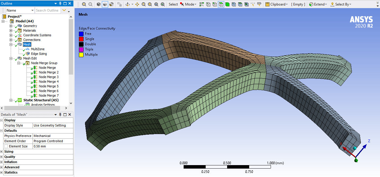
SubscriberSlice the geometry up into one small piece in SpaceClaim. Use the Mirror feature to make more pieces and make sure to uncheck Merge mirrored objects so that you have separate pieces in the end.
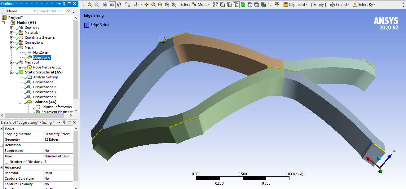
In Mechanical, use Multizone on all the bodies. Add a Mesh Sizing to force a desirable edge count, but use Behavior = Hard.
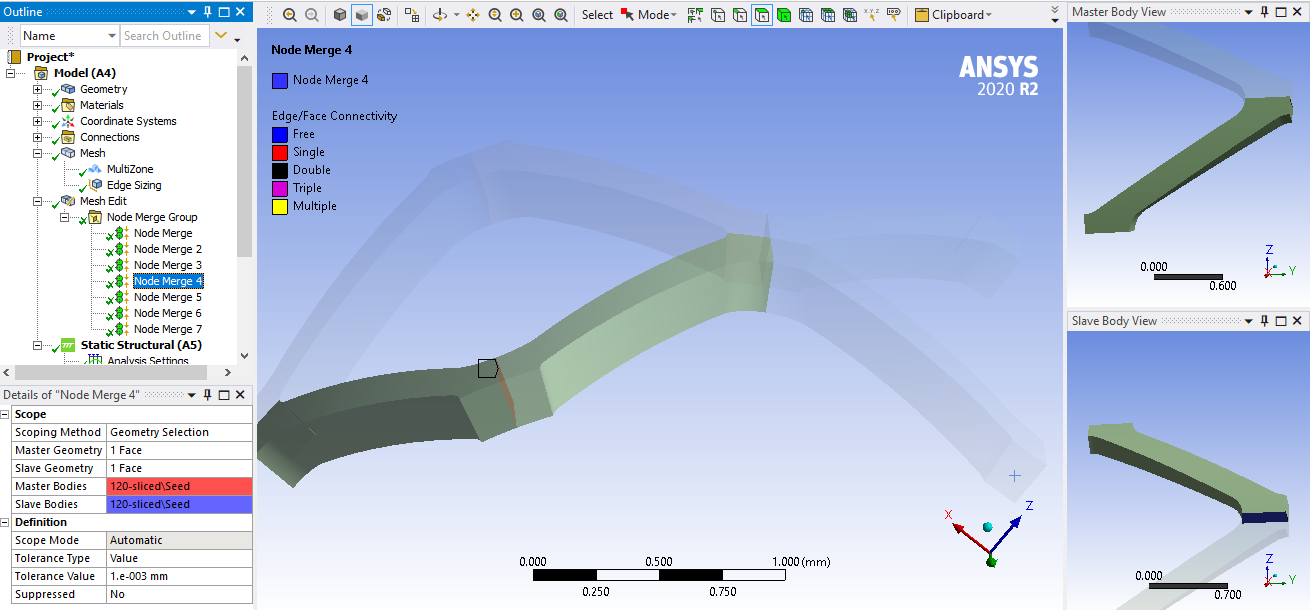
Add a Mesh Edit which can automatically detect all the faces that need to have the nodes merged.
-
August 9, 2023 at 11:44 am
Arash Kavosi
Subscriberthank you for your advice. but after meshing of the parts, how do I can attach them to acheive the complete stent? finally I should displace the stent not separated parts individually
-
August 9, 2023 at 2:40 pm
peteroznewman
SubscriberThe Mesh Edit, Node Merge Group is what holds the individual parts together into one large stent.
I only mirrored a small part of the whole stent. You can mirror more of the stent until you have a complete circle and the length you want, but a 1/4 model is sufficient to observe the displacement you want.
-
- The topic ‘displacement in 2 ends simultaneously’ is closed to new replies.


-
3477
-
1057
-
1051
-
945
-
912

© 2025 Copyright ANSYS, Inc. All rights reserved.

