Fluids

Fluids

Topics related to Fluent, CFX, Turbogrid and more.

Different results for inlet boundary conditions.

    • venkyvenkatesh374
      Subscriber

      Hello All, Greetings for the day.

      Am working on a project to determine lift force generated by a 3d wing at different AOA.,

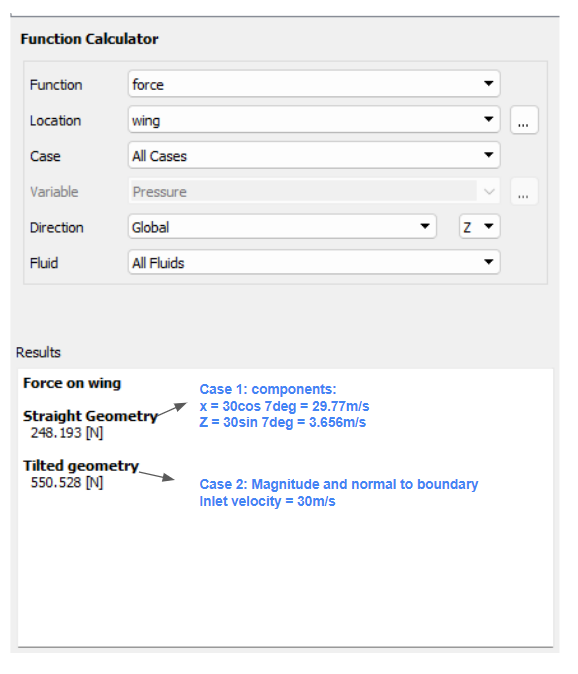
      In first method I tilted the geometry to 7deg and gave velocity inlet normal to boundary condition, I got a result around 550N, In second method i kept the geometry straight and gave components in X and Z coordinates ( Refer snip ) where lift generated is around 248N.

      keeping turbulence model and other conditions same, am getting different results. I have enclosed snips for your reference. Please help me understand where am going wrong.

    • abhishek.roy
      Ansys Employee

      When titing the geometry if you want to maintain same AOA the chord of the wing should be rotated with respect to horizintal axis. If the wing is twisted titling might make it difficult to get desired AOA. Usually velocity component approach is preferable. 

    • venkyvenkatesh374
      Subscriber

      Thanks for the reply sir., I did the same how yu've mentioned. for some reason the results are different.

      Also I tried another method, where I've set a user defined coordinate frame which is tilted to specific angle of attack. Now while solving the case Ansys uses default coordinate frame. Anychance do you know how to set the user defined coordinate frame while solving the case. 

    • abhishek.roy
      Ansys Employee

      Refer to the following link
      6.4. Reference Frames

    • venkyvenkatesh374
      Subscriber

      Sir, In This its excplained how to create an new refrence frame, and how to create point and surfaces on that reference frame. My query is to how to set this refrence frame to solve the case. 

Viewing 4 reply threads
  • You must be logged in to reply to this topic.