We have an exciting announcement about badges coming in May 2025. Until then, we will temporarily stop issuing new badges for course completions and certifications. However, all completions will be recorded and fulfilled after May 2025.
General Mechanical

General Mechanical

Topics related to Mechanical Enterprise, Motion, Additive Print and more.

Difference in force-deflection curve (Remote displacement vs Loading Plate)

    • Rommel Jr. Landicho
      Subscriber
      Hi everyone!
       
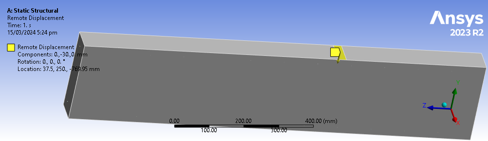
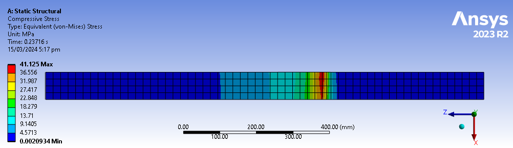
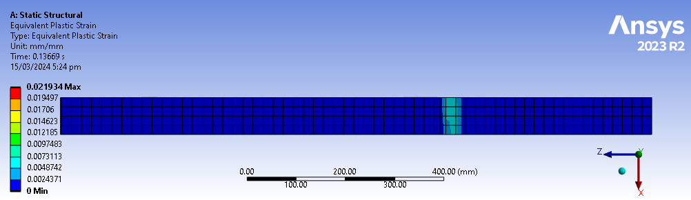
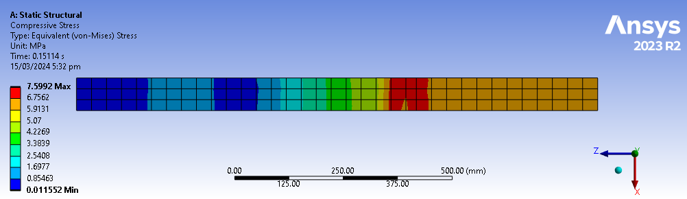
      I'm trying to model an RC beam subjected to 4 point bending test. I am doing a displacement-controlled model using remote displacements directly on the face of the beam but I noticed that the stresses and strains are concentrated on that face itself. In reality, the middle portion of the beam (to the right of the face) should be experiencing higher stresses and strains, which is not the case in my model as shown. 
       
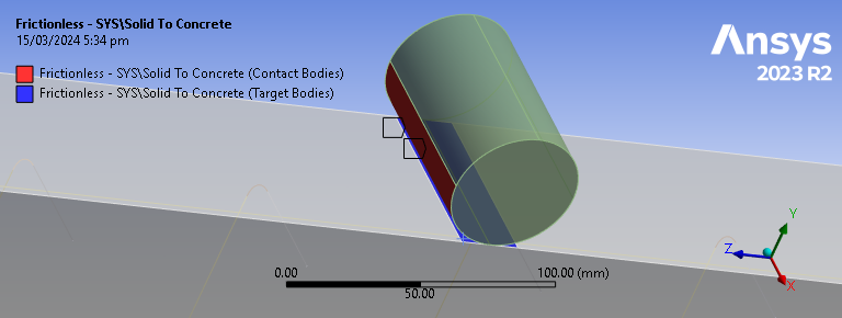
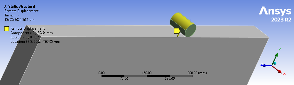
      Because of this, I tried modelling with a circular loading with the following configuration. The contact region is frictionless with adjust to touch interface treatment while the others are program controlled. 
       
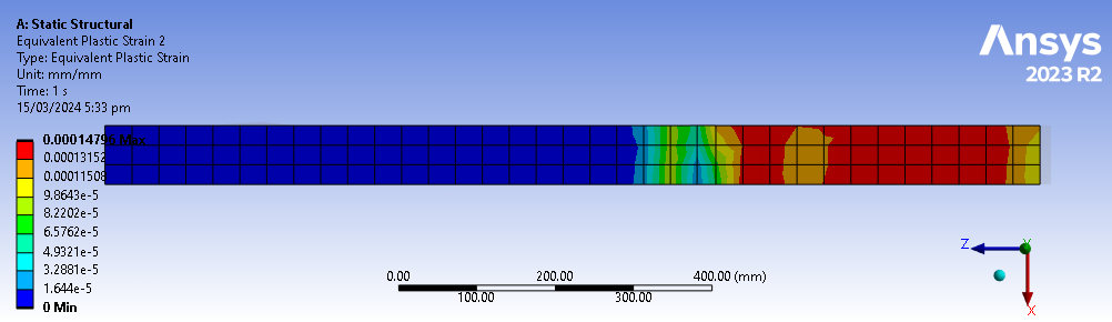
      In this way, the stresses and strains are better distributed at the top of the beam rather than being concentrated on the loading face of the beam as shown below. 
       
      However, my problem here is that the forces are greatly underestimated. My initial model (the one without loading plates, only remote displacements at the face) had fairly accurate load-deflection curves. However, the forces in this model are greatly reduced to more than half of the values in my initial model. I tried varying the contact surface of this model but some of them cause nonconvergence. 
       
      With that, I have 2 questions:
       
      1. What can I do with my first model so that the stresses and strains are not concentrated at the loading face itself?
      2. What can I do with this current model so that the values are not underestimated?
       
      Thank you!
    • Erik Kostson
      Ansys Employee


      Hi

      See if this tutorial (link below) helps. So just use a displacement with y non zero and x and z free on an edge – so do not use a remote displacement with all zero except of y of course. The tutorial also shows how to extract the failure load (force reaction of imposed displacement).

      As for why you get different values, could be many things (material properties etc.) . In theory it could be able to capture the failure of a RC beam.

      Some test cases where it has been used: https://www.researchgate.net/publication/354765497_Calibration_and_Validation_of_the_Menetrey-Willam_Constitutive_Model_for_Concrete.

      /forum/forums/topic/how-can-we-model-failure-in-reinforced-concrete-rc-slabs/

      All the best

      Erik


Viewing 1 reply thread
  • The topic ‘Difference in force-deflection curve (Remote displacement vs Loading Plate)’ is closed to new replies.