-
-
April 2, 2023 at 9:18 am
-
April 2, 2023 at 11:22 am
peteroznewman
Subscriber
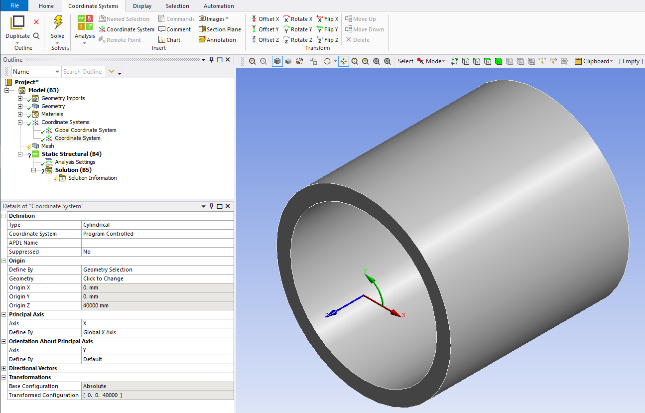
Place a Cylindrical Coordinate System on the cylinder axis, with the Z axis pointing along the cylinder axis. The X coordinate measures Radial deformation.
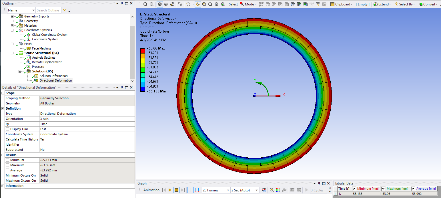
Add a Directional Deformation, set it to use the Cylindrical Coordinate System and to plot the X coordinate. The contours will be radial deformations.
Since you know the initial radius of the cylinder, subtract the radial deformation and double that to get the compressed diameters.
-
April 2, 2023 at 4:53 pm
thach-hoang.nguyen
SubscriberThank you for the ideal! But i have the problem that i dont know how to set up for the cylinder axis. If it's not too bother you, can you make an exemple for me how to set it up to calculate the radial deformation?
Thank you so much! Have a great day
-
April 3, 2023 at 8:11 pm
-
April 3, 2023 at 8:17 pm
-
April 4, 2023 at 7:15 am
thach-hoang.nguyen
SubscriberThank you so much! Another question i have to ask: How can you use the remote displacement to hold the cylinder when doing the test! Thank you!
-
April 4, 2023 at 9:44 pm
peteroznewman
SubscriberUse a Remote Displacement, Behavior = Flexible, scoped to one end face of the cylinder. Set all DOF to 0.
-
- The topic ‘Diameter of a cylinder after deformation’ is closed to new replies.
-
5859
-
1906
-
1420
-
1305
-
1021
© 2026 Copyright ANSYS, Inc. All rights reserved.


