-
-
November 7, 2024 at 1:47 am
-
November 7, 2024 at 6:49 pm
Guilin Sun
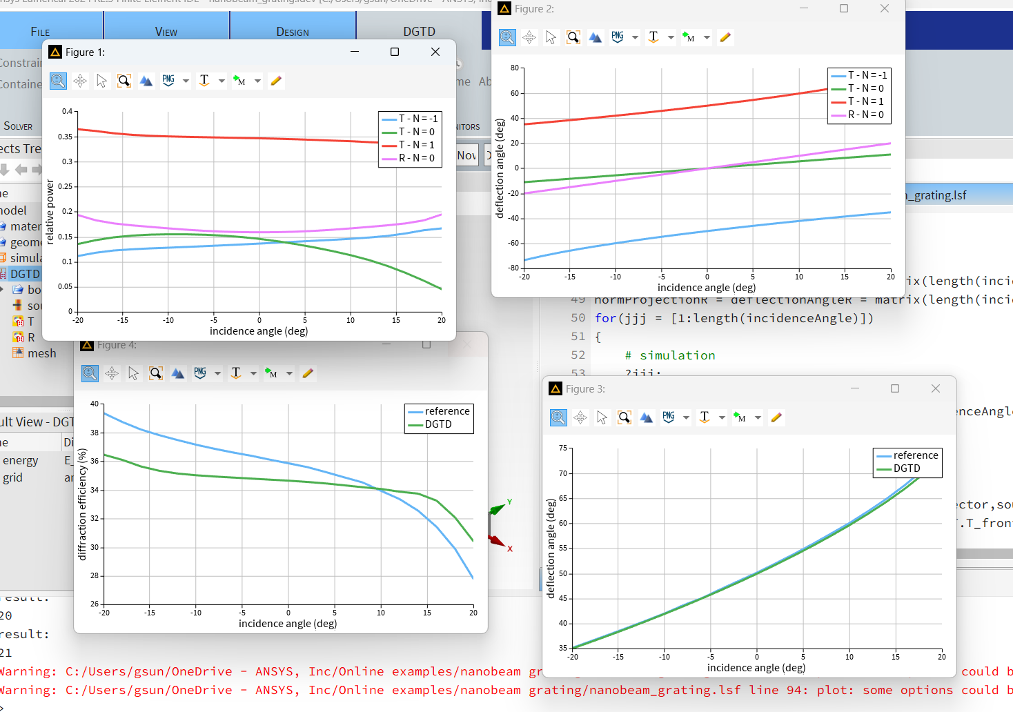
Ansys EmployeeI tested the online version and it works fine:

the warning sign is just showing warning, it does not effect the simulation result.
Your script seems different from the online one, guess it is old version.
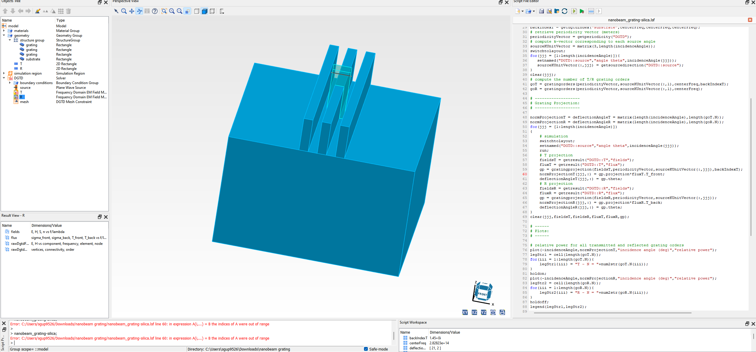
Please download the newest version and test again. if the problem still exists, please use question mark to check the dimension of the matrix:
?size(normProjectionT)
?jjj;
-
November 15, 2024 at 3:48 am
sgup9526
SubscriberHi there,
Thanks for the help!
The model works now. The online example plots the relative power and the diffraction angle. Other than that, I need to observe the phase change with the angle and the width variation of the grating.
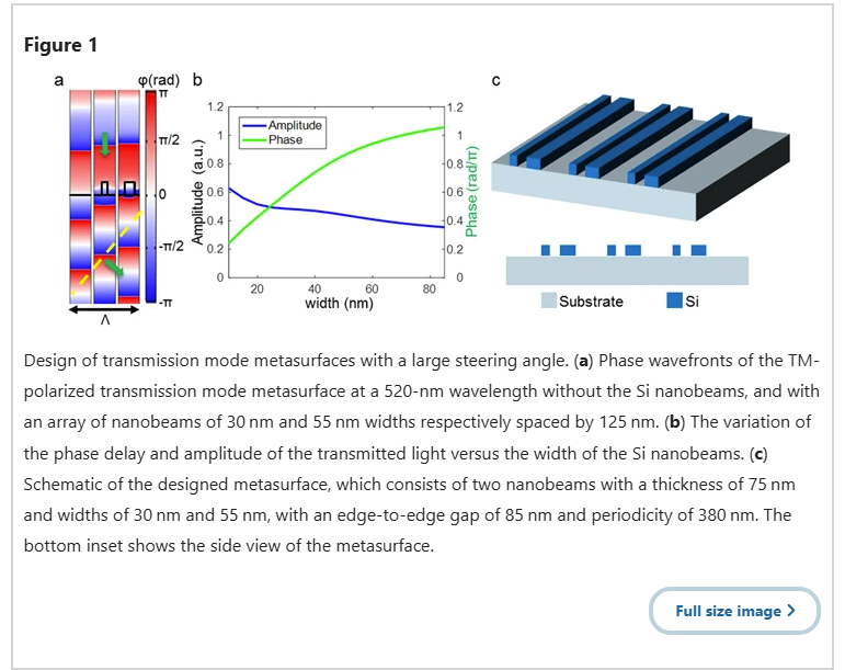
The research paper of this online example - 'Lin et al,. "Optical metasurfaces for high angle steering at visible wavelengths", Scientific Reports, 7, 2286 (2017)', has plotted the 1D and 2D phase results for the different grating widths (see the attached screenshot).
I need to observe these data for my model as well. How to extract phase profile (1D and 2D) in DGTD?
Thanks!
Shashank
-
November 15, 2024 at 8:29 pm
Guilin Sun
Ansys EmployeeHi Shashank,
This is a different question to the original post. Later please write a new post. Since I will be away for some time from next week, if you still have questions please write a new post since no others in support will come here to check.
In order to plot the phase, you will need get the complex farfield for the grating: https://optics.ansys.com/hc/en-us/articles/360034407034-gratingpolar-Script-command however most often there will have s and p (theta and phi) components and they may be not the same. So you will need to choose which one is to use. However, the gratingpolar gives the phase from the monitor to 1m away sphere, and there propagation phases from source to grating front, and from grating back to monitor, plus the far field 1m. You will need to compensate those phases analytically:
https://optics.ansys.com/hc/en-us/articles/360042095873-Metamaterial-S-parameter-extraction
https://optics.ansys.com/hc/en-us/articles/360042097393-Metamaterial-parameter-extraction-Smith
Due to numerical error, I would suggest to have the source and the monitor close to the grating (maybe 2 or few mesh distance).
TO create Fig.a and FIg.b plosts, you will need to sweep the period and width: https://optics.ansys.com/hc/en-us/articles/360034922873-Parameter-sweep-utility
Please try and write a new post for any questions. Thank you!
-
- You must be logged in to reply to this topic.


-
3432
-
1057
-
1051
-
902
-
896

© 2025 Copyright ANSYS, Inc. All rights reserved.


