Photonics

Photonics

Topics related to Lumerical and more.

Designing a single mode fiber

    • jiglesi1
      Subscriber

      I designed a Lumerical Mode Solution rectangular Si waveguide with Si substrate and adjusted the width and thickness in order to achieve one TE mode. I want to now design a single mode fiber where the indices of the fiber core and cladding are 1.6 and 1.4. However I am still somewhat new to Lumerical and have never designed a fiber on it. I can use some advice on if I should take my existing design and tweak the geometry to make my fiber design while keeping the single mode, or should I just do a brand new design for the single mode fiber? In order to design the fiber, am I just creating two cylinders or circles with the core in between the cladding? Any advice is greatly appreciated. Thank you!


    • Guilin Sun
      Ansys Employee

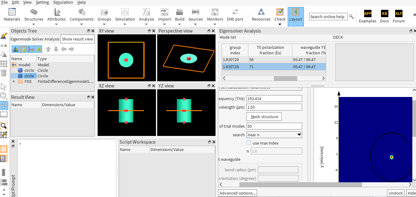
      You can either based on existing example or from scratch. YOu can use a cylinder as the core and a ring as the clading, or even two cylinders (circle). Since Lumerical uses mesh override the geometry https://optics.ansys.com/hc/en-us/articles/360034915233-Understanding-mesh-order-for-overlapping-objects you may first create the cladding, and change the core radius.

      Other than TE mode, do you have other requirements?  I believe crearing a fiber to have TE mode is easy. But with other requirements you may need to spend time to optimize, or parameter sweep.

      https://optics.ansys.com/hc/en-us/articles/360042798673-SMF-28-fiber-mode-calculation

      https://optics.ansys.com/hc/en-us/articles/360034901513-Circle-Simulation-Object

      https://optics.ansys.com/hc/en-us/articles/360034382194-Ring-Simulation-Object

      https://optics.ansys.com/hc/en-us/articles/360034922873-Parameter-sweep-utility

    • jiglesi1
      Subscriber

      Thank you Guilin Sun for your reply. What I have done so far is I found a Lumerical page https://optics.ansys.com/hc/en-us/articles/360043165394-Fibers-List-of-Examples that has fiber files to use and I downloaded the step index FDE file since technically my single mode fiber is a step index fiber. I attached my pics of my single mode fiber design and the calculations I used to design the geometry of the waveguide. The calculations for the radius of the core gave me a radius of .7659 um. I made the cladding radius 10 times the core radius so cladding radius is 7.659 um. The FDE I designed to have an x span and a y span of 38 um each. After calculating the modes I get two modes. I cannot seem to design to generate one mode only. I also included plots of my two modes. Can someone please let me know how I can tweak my design to get only one mode? Any advice is welcome.


    • Guilin Sun
      Ansys Employee

      Ibelieve that two modes you get are correct: they are degenerated TE and TM modes. Their mode profile is the same with the same neff. If you use some  kind o fsymmetry BCs, one will disappear. For example, you can use xmin anti-symmetric, and ymin symmetric. You can check the SMF example.


Viewing 3 reply threads
  • You must be logged in to reply to this topic.