TAGGED: #fluent-#ansys, fluent, fluent-mesh, layering
-
-
May 28, 2025 at 9:28 pm
zoelle.wong
SubscriberDear ANSYS Universe,
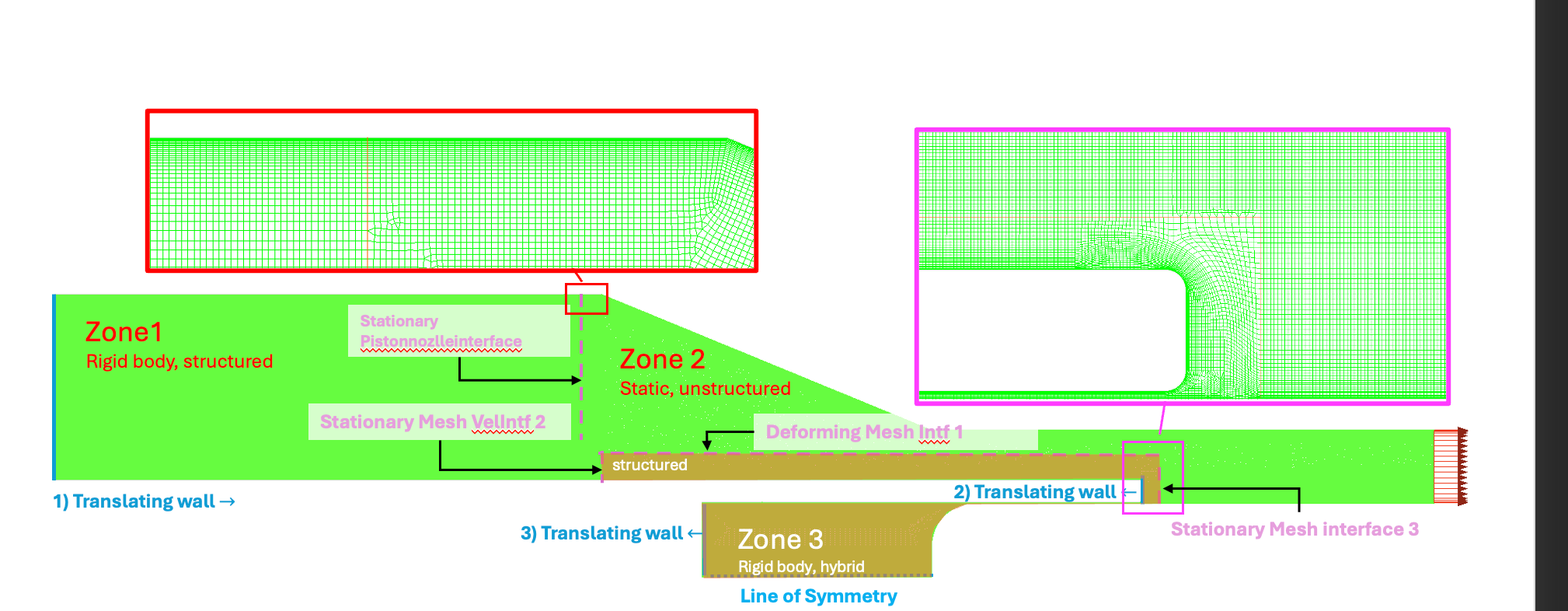
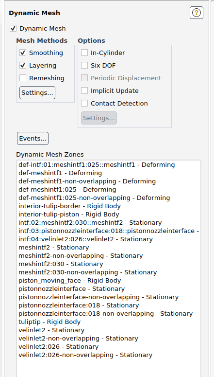
I am trying to include a dynamic mesh with the boundary conditions illustrated below. I've done this before with a coarser mesh, where refinement normal to the wall was not added. However for the case below, I get the following error: "Corrupted double-linked list; received signal SIGSEGV". I found that the deforming mesh-interface (def-meshintf1) and the motion of zone2. Other internal dynamic mesh boudnaries converge. Would forcing the entire domain to be structured cells potentially fix this problem? I have also attached the boundary conditions that I am specifying to clarify. Thank you again so much!
-
May 29, 2025 at 12:24 pm
Federico
Ansys EmployeeI think the fact that your 'layers' are not uniform could be causing problems. Are you using height-based or ratio-based Layering?
A structured approach would definitely be cleaner.
-
May 29, 2025 at 12:27 pm
zoelle.wong
SubscriberHeight-based!
I wasn't able to make a structured mesh very well in Zone 2 due to the curved surfaces.. The aspect ratios were still too high despite smoothing. If I made Zone 2 bigger to give more space for the cells to "un-warp" could that help with layering?
Thank you!@
-
May 29, 2025 at 12:28 pm
zoelle.wong
Subscriber*zone3 my mistake
-
May 29, 2025 at 9:45 pm
zoelle.wong
SubscriberI went back and added structured cells adjacent to all the interface boundary conditions, but I'm still getting the same error. I'm very sure it's related to the deforming boundary condition imposed on "Deforming Mesh Intf1". I've tried different values for the collapsing and spitting factor which did not solve the problem.
Zone1 cells collapse at "Stationary Piston Interface".
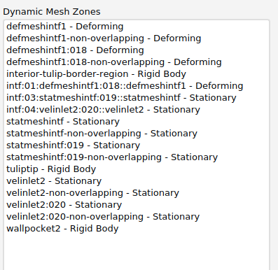
I'm copying/pasting the boundary conditions I put on Zone 2 below. WallPocket2 is the 3) Translating Wall in the figure above. Thank you in advance!
-
May 30, 2025 at 8:55 pm
zoelle.wong
SubscriberHello!
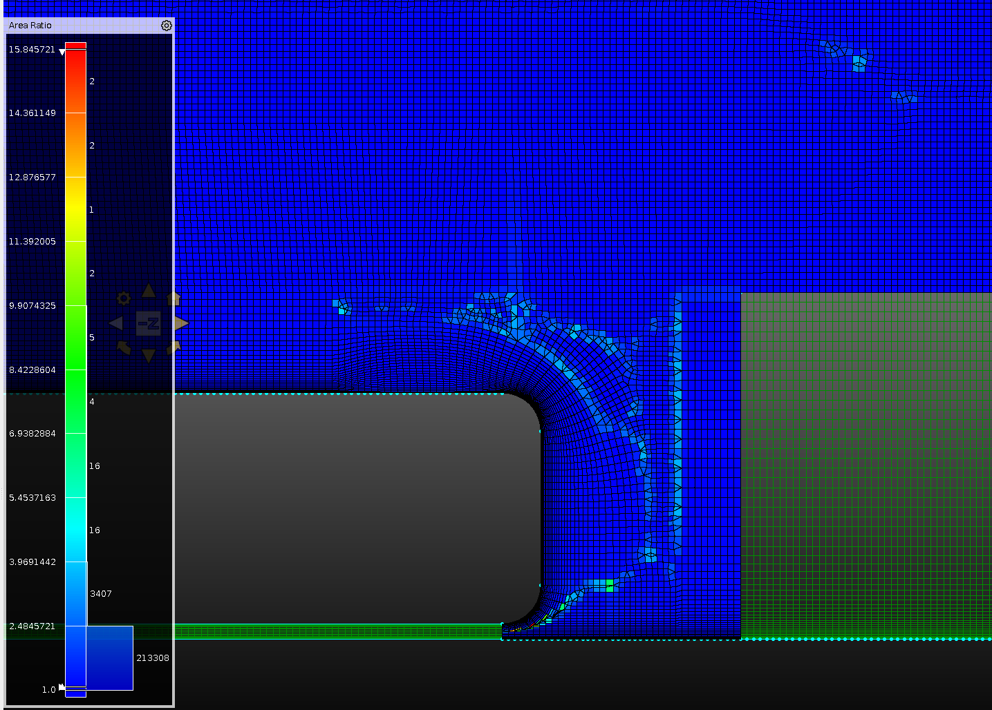
I'm pretty sure that the SIGSEGV error comes from the mesh quality at the deforming boundary condition and not from my UDF. For zone 2, I broke it up into smaller pieces comprised of structured and unstructured blocks, but at the deforming interface, I have some cells at the deforming interface that don't have a 1:1 Area Ratio. If this is the case, does a deforming mesh interface need a 1:1 Area ratio? I know padding interfaces with cells to make a non-conformal interface ensures stability and that information is passed along more accurately to nodes. Wanted to clarify if this could be a key cause. Thank you!
-
- You must be logged in to reply to this topic.


-
4602
-
1510
-
1386
-
1209
-
1021

© 2025 Copyright ANSYS, Inc. All rights reserved.


