Hello,
So, I am trying to run a simulation on a screw that is connecting two plates together with a small distance in between. There are two things i am trying to achieve: first, to determine whether or not the plate itself will break and second, whether or not the screw itself would break.
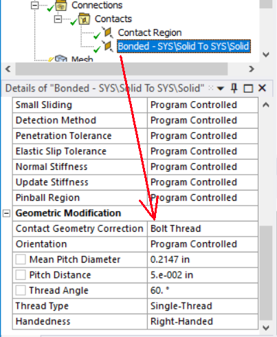
Looking at the picture attached, I am struggling with identifying what boundary conditions to apply on my part. In its real application, this part is fixed from the upper link, while the lower link inside of it is connected to a part from which force is exerted downward. So, with this in mind I applied all the required contact with the screw and the parts and have applied a fixed boundary on top and then on the bottom of the second link i applied a force downward. However, this does not seem to accurately mirror the real application as i cannot see any much of a stress concentration around the screw area, and if any deformation should ocurr it should be in that area. Is there anyone that has experience or knowledge in this area that could clarify what I could be missing? Should I be simulating each component separately instead?
I would appreciate any help.
Boudnaries:
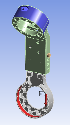
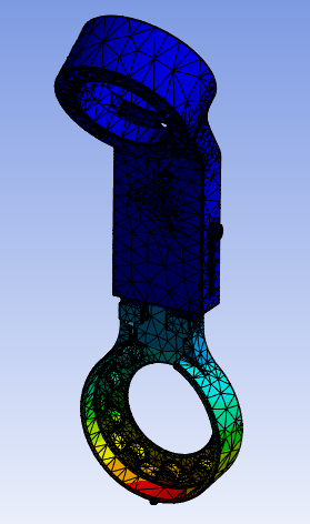
Deformation:
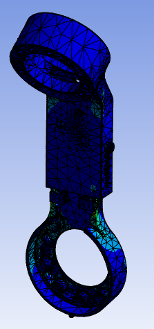
Stress: