We’re updating our badges platform. Badge issuance is temporarily paused, but all completions are being recorded and will be fulfilled once the platform is live. Thank you for your patience.
Photonics

Photonics

Topics related to Lumerical and more.

DBR structure instablility Lumerical FDTD

    • nguyben
      Subscriber

      I am attempting to simulate a DBR structure in lumerical with a cavity. However, I am running into divergence issues. Using a movie monitor, I see that the simulation begins as usual. However, once the autoshutoff level reaches around 0.005, it starts increasing again. Interestingly, it appears as if a large amount of power is appearing in the silicon layers.

      I am using a steeped angle PML. with 40 layers. Furthermore, following the article https://optics.ansys.com/hc/en-us/articles/11277217507603-Troubleshooting-diverging-simulations-in-FDTD , and setting all boundaries to metal, I find that the results are close to 0 but not diverging. I have checked the materials and there are no imaginary indexes at any point. I am using the default settings for material fit.

      Are there any tips or advice I can follow? Thanks

    • Kirill
      Forum Moderator

      Dear Subscriber, 

      To assist you better, please share a screenshot of the Lumerical CAD > Help > About... page, similar to the one in this image. 

      Thank you! 

    • nguyben
      Subscriber

      [ The image has been deleted. ] 

      I am currently using the student trial


    • nguyben
      Subscriber

      I have found that a very small dt stability factor of less than 0.07 is necessary for good simulations. Unfortunately, these simulations take quite a while. Since I am using BFAST, the normal symmetry boundary conditions are not available to me and I am running at accuracy level 2. Is there any advice on how to further speed up simulation?

    • anna.wirth-singh
      Ansys Employee

      Hi,

      Thanks for question and for your patience! I can offer a few suggestions, but it sounds like you are already on the right track for troubleshooting the problem. Using a movie monitor to try to identify the source of divergence is a great start.

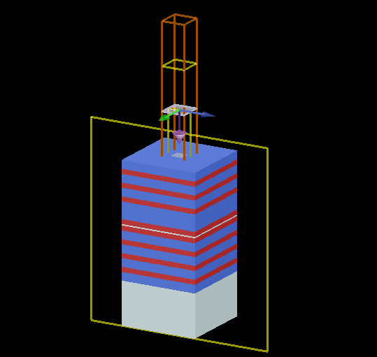
      For a diverging simulation where the divergence appears inside a material, a material fitting issue is often the source of the problem. It is definitely good to check that there is no imaginary part to the material at any point over your entire simulation bandwidth, but it sounds like you have already ruled this out.

      Are you running your simulation on CPU or GPU? In some circumstances, the GPU solver is known to be less stable. You can try running on CPU instead if you are not already doing so.

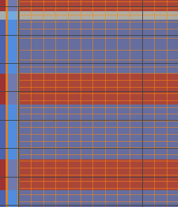
      Another possibility, which is less common but can still occur, is that a large mesh aspect ratio can cause instability. If your layers are very thin, possibly the mesh in the z direction is much finer than the mesh in the x and y direction. You might  be able to reduce dt if you can make the x, y, and z meshes more equal, but then to obtain the same level of accuracy you may need to use a finer mesh so there will be a tradeoff between memory and simulation time.  

      I hope this helps!

      Best,

      Anna

      • nguyben
        Subscriber

        I have increased the mesh x and y direction meshes smaller with a mesh override region such that it looks like this

        I've tried a few different x and y mesh sizes and also changing the accuracy level of the fdtd. Also, some different dt values and increased pml layers. In the end, the autoshutoff level always ends up somewhere around 0.002-0.004.

        I believe this is causing undesired peaking in the reflection results. The movie monitor does not reveal any obvious problems which makes sense since there is little energy left in the simulation, so I would not be able to see anything.

        The simulation does not seem be unstable though. Do you believe that increasing accuracy further would be beneficial? The simulation time is already at quite a long time so I am hesitant to increase it more.

    • anna.wirth-singh
      Ansys Employee

      Hi, thanks for the additional information. I think your results are reasonable – since there is a cavity in your DBR structure, it is likely expected that some light will become trapped and take a long time to decay. From the autoshutoff trending downwards, I think we have solved the problem of the diverging simulation.

      For cavities, you will generally achieve better results by simulating for a longer period of time and allowing the field to fully decay, however this might take a longer amount of time than it is feasible to simulate. A field that is not fully decayed may cause some unexpected peaks in T/R results, as you say. We have some postprocessing techniques for high-Q cavities. You may be able to shorten the simulation time and use postprocessing techniques to extract quantities like resonant frequencies and quality factors based on the envelope of the decay without simulating all the way to a low autoshutoff level, as described here: https://optics.ansys.com/hc/en-us/articles/360041611774-Quality-factor-calculations-for-a-resonant-cavity

      Please take a look and let us know if this approach seems applicable to your simulation. 

Viewing 5 reply threads
  • You must be logged in to reply to this topic.