
-
-
April 1, 2021 at 8:33 pm
Sam1
SubscriberHi,
I am modeling a lug-like structure in static structural linked from ACP and wanted to use a cylindrical support for the hole. However, I was unable to select the geometry using either the shell or the solid model from ACP. When I click on the edge/face by itself, the entire circle is highlighted and in CAD, it was created on a flat plane. Is there something I am missing or a potential work around?
April 5, 2021 at 6:52 am1shan
Ansys Employee,nI don't fully understand your question. Do you mean that the geometric features that existed in ACP are not visible/selectable in static structural? Please check this /forum/discussion/2831/geometry-areas-and-symmetries-transfer-after-acp and see if it helps.nRegards,nIshan.nApril 14, 2021 at 5:04 pmSubscribernTo clarify what I was asking, I meant that the edge of the circle/face created in either shell/solid model from ACP. is selectable in the following static structural and it is highlighted when I click on it. But when I go to try and apply a cylindrical support, it is not able to select it as a usable support. nApril 15, 2021 at 11:04 amAnsys Employee,nYou could try a work around. Create a cylindrical coordinate system at the center of the hole with proper orientation. Using node selection select all the circumferential nodes, RMB> named selection. Then insert a nodal orientation object, scope it to the named selection and the cylindrical coordinate system (this will orient the nodes in the new coordinate system). Next insert a nodal displacement, scope it to the named selection and then specify the DOFs (which will now be in the cylindrical coordinates).nRegards,nIshan.nApril 21, 2021 at 8:31 amSubscribernIs this the correct setup for this type of part? I made a 5 ply composite plate with a hole that would have a bolt going through so it behaves like a tab. A force would be applied on the top face. For the solid geometry exported from ACP, I selected the node at each ply, so there were a few going across and then around the circle. I didn't try the shell geometry yet. For the nodal displacement, I fixed it in the x and z direction of the cylindrical support to imitate tangential and axial constraints. However, it was not able to solve. n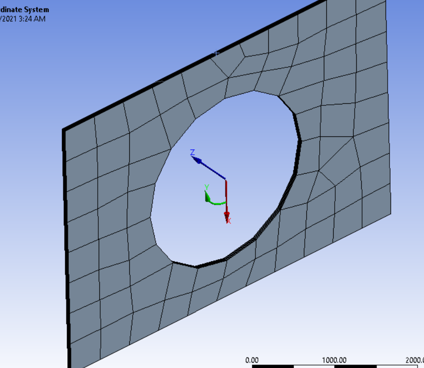 n
n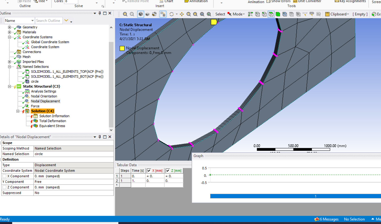 n
April 21, 2021 at 12:43 pmAnsys Employee,nWhat errors do you get?nIshan. nApril 21, 2021 at 3:11 pmSubscribernI've had a combination of these errors:nSolver pivot warnings or errors have been encountered during the solution. This is usually a result of an ill conditioned matrix possibly due to unreasonable material properties, an under constrained model, or contact related issues. Check results carefully.nA solver pivot warning or error has been detected in the UY degree of freedom of node 718 located in SolidModel.1. This is usually a result of an ill conditioned matrix possibly due to unreasonable material properties, an under constrained model, or contact related issues. Check results carefully. You may select the offending object and/or geometry via RMB on this warning in the Messages window.nNot enough constraints appear to be applied to prevent rigid body motion. This may lead to solution warnings or errors. Check results carefully.nnIn real life, these pieces are like tabs on a composite piece experiencing loading and the bolts go through the tabs to mount on another piece.nApril 22, 2021 at 4:31 amAnsys Employee,nI see that you have a free rotation DOF (along y) right? This will likely case the plate to rotate, when a force is applied, which is likely the reason for pivotal error. When you have a bolt going through a washer, it exerts pressure on the surface of bolt and the resulting friction force between washer and mating surface prevents it for rotating, right? Since you have not considered the friction force here you have to provide an additional constraint to the washer. Either fix the Y rotation (which will be equivalent to a fixed support) or give zero displacements ( free only the normal to plate direction) to the sides .nRegards,nIshan.nViewing 7 reply threads
n
April 21, 2021 at 12:43 pmAnsys Employee,nWhat errors do you get?nIshan. nApril 21, 2021 at 3:11 pmSubscribernI've had a combination of these errors:nSolver pivot warnings or errors have been encountered during the solution. This is usually a result of an ill conditioned matrix possibly due to unreasonable material properties, an under constrained model, or contact related issues. Check results carefully.nA solver pivot warning or error has been detected in the UY degree of freedom of node 718 located in SolidModel.1. This is usually a result of an ill conditioned matrix possibly due to unreasonable material properties, an under constrained model, or contact related issues. Check results carefully. You may select the offending object and/or geometry via RMB on this warning in the Messages window.nNot enough constraints appear to be applied to prevent rigid body motion. This may lead to solution warnings or errors. Check results carefully.nnIn real life, these pieces are like tabs on a composite piece experiencing loading and the bolts go through the tabs to mount on another piece.nApril 22, 2021 at 4:31 amAnsys Employee,nI see that you have a free rotation DOF (along y) right? This will likely case the plate to rotate, when a force is applied, which is likely the reason for pivotal error. When you have a bolt going through a washer, it exerts pressure on the surface of bolt and the resulting friction force between washer and mating surface prevents it for rotating, right? Since you have not considered the friction force here you have to provide an additional constraint to the washer. Either fix the Y rotation (which will be equivalent to a fixed support) or give zero displacements ( free only the normal to plate direction) to the sides .nRegards,nIshan.nViewing 7 reply threads- The topic ‘Cylindrical Support in ANSYS ACP’ is closed to new replies.
Innovation Space Trending discussions
 Top Contributors
-
peteroznewman
 4989
4989 -
scabo
 1665
1665 -
Dennis Chen
 1386
1386 -
javat33489
 1242
1242 -
Shyam Prasad V Atri
1021
Top Rated Tags
© 2026 Copyright ANSYS, Inc. All rights reserved.
Ansys does not support the usage of unauthorized Ansys software. Please visit www.ansys.com to obtain an official distribution.
-


The Ansys Learning Forum is a public forum. You are prohibited from providing (i) information that is confidential to You, your employer, or any third party, (ii) Personal Data or individually identifiable health information, (iii) any information that is U.S. Government Classified, Controlled Unclassified Information, International Traffic in Arms Regulators (ITAR) or Export Administration Regulators (EAR) controlled or otherwise have been determined by the United States Government or by a foreign government to require protection against unauthorized disclosure for reasons of national security, or (iv) topics or information restricted by the People's Republic of China data protection and privacy laws.


