General Mechanical

General Mechanical

Topics related to Mechanical Enterprise, Motion, Additive Print and more.

Creep anaysis on a plastic component – Analytical and ANSYS results don’t match

    • Jacopo Bardiani
      Subscriber

      Hello everyone,


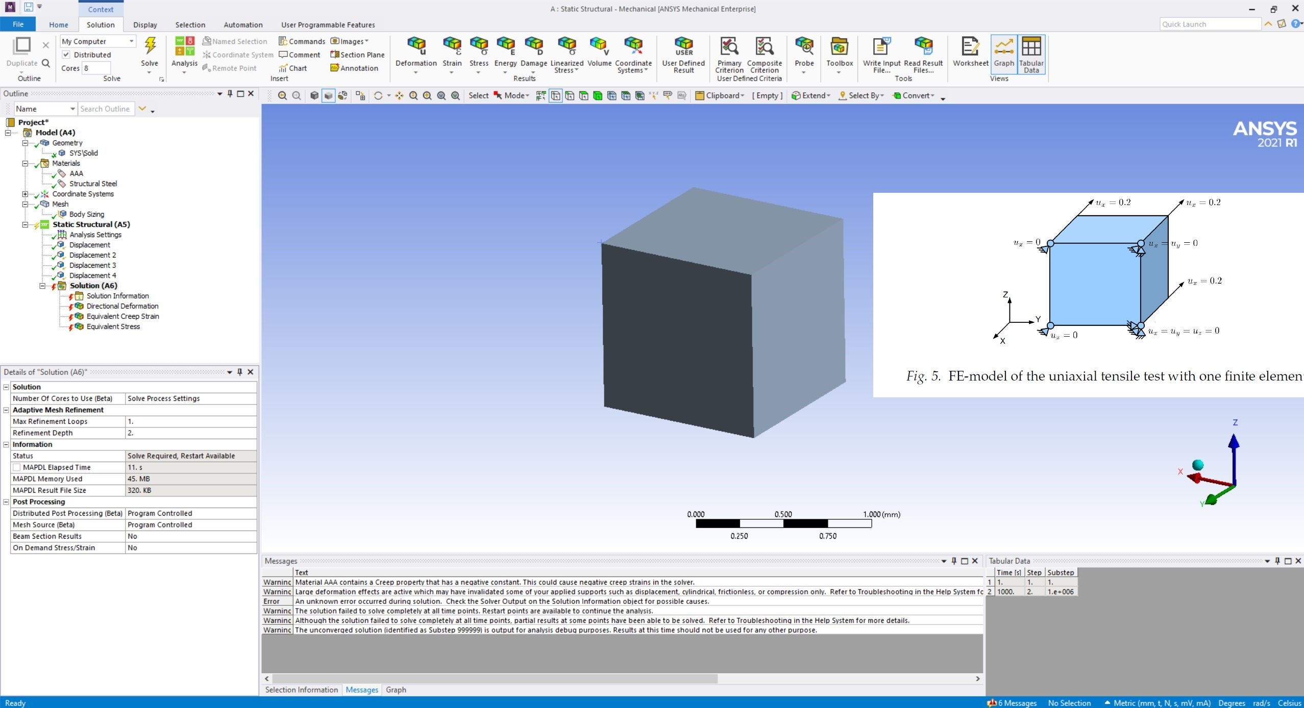
      I'm doing a "Static Structural" analysis on a plastic cover, in order to study the creep behavior. Given the double symmetry of the plate, I study only 1/4.


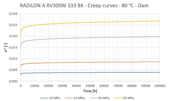
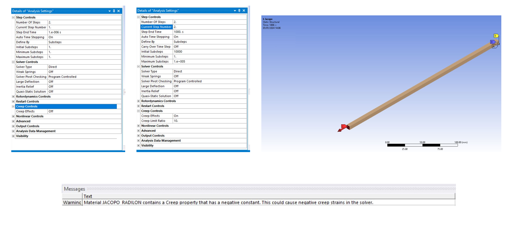
      I have all the experimental info of the material under examination (sigma-epsilon curves and creep curves) and I tried to set up the analysis on ANSYS Workbench. I implemented an elasto-plastic material, with the appropriate module and with the parameters of the creep model (Time Hardening Power Law, using the ANSYS fitting tool).


      I then set up two steps: in the first, very short, I apply the constraints + loads (a known pressure on one side of the component) without considering the creep. In the second step, I activate the creep and have constant pressure (I study for example 4 hours).


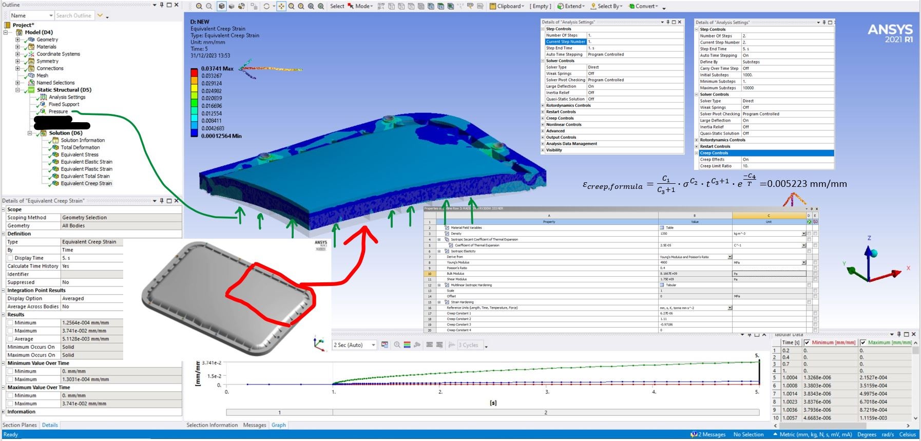
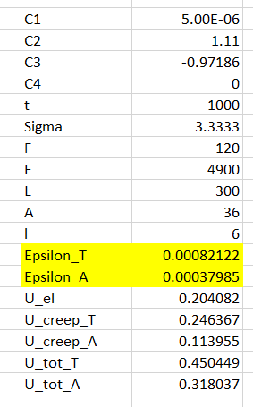
      The constants of the Time Hardening Power Law model are C1 = 6.27 E-06, C2 = 1.11, C3 = -0.97186, and C4 = 0. The constants were calculated taking into account MPa and hours.


      The total deformation of the plate after 5 hours is 10 mm. After the first step, it deforms by 0.6 mm.


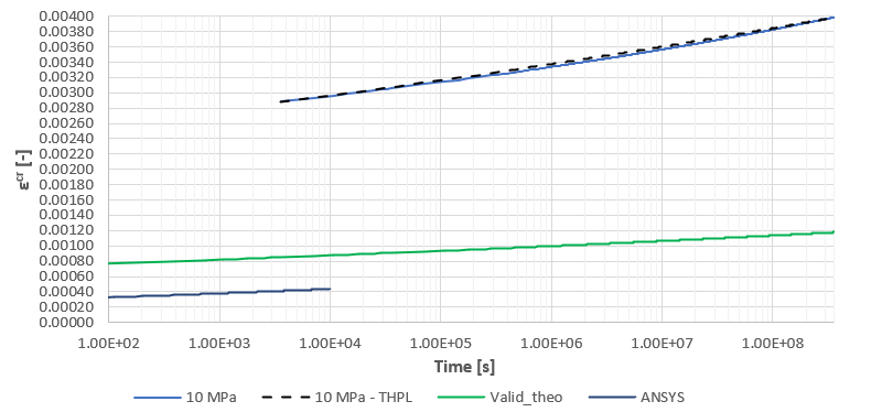
      Simulating 4 hours of creep (step 1 = 1 hour and step 2 = 4 hours), I get a maximum equivalent creep strain of 0.037, while from the analytical formula of the Time Hardening Power Law model (using t = 4 hours and the constants), I get 0.005.


      What could be causing this discrepancy?


      Thanks in advance.


    • peteroznewman
      Subscriber

      Creep Constants in Ansys assume time is measured in seconds.  You used 1 second to represent 1 hour in the analysis and you fit the constants to the data making the same substitution. Maybe that ends up cancelling out, I am not sure.

      In the past, I made a simple square profile of a long rod under tension.  See my June 1 post in this discussion. In my model, the stress was uniform. My hand calculation exactly matched the Ansys result. You can do the same with your constants and if you don’t get an exact match using the constants with the time units of hours, try again with seconds.

      • Jacopo Bardiani
        Subscriber

        First of all, thank you very much for your reply!

        I've seen other threads where you've responded to creep analysis.

        It seems to me that since we are in a "Static Structural" analysis, we can use a "fictitious" time unit of measurement based on the units of measurement of constants. C2 and C3 are dimensionless while C1 has MPa^(-C2) * hours^(-C3-1) as a unit of measurement.

        In many threads, this same approach was applied with these units of measurement (see https://www.youtube.com/watch?v=9DYFSck8h-M&t=2101s).

        What do you recommend I do? Do I set C1 so that it has seconds as the unit of measurement and set step 2 as 3600x5 seconds?

        Could the discrepancies be due to the fact that in my case the plate is in bending and not in pure traction? In my case, the plate hasn’t a constant stress field like in a tensile specimen.

        Let me know.

      • Jacopo Bardiani
        Subscriber

        Hi Peter,

        Happy New Year! I've tried as you told me and the results change a lot! Now I obtained an equivalent creep strain of 0.0015 while the analytical formula gives me 0.005. 

        It's better than before, but I'm not able to understand if I'm wrong or the results are plausible. My situation is really different from the real creep test so I don't know if my model in ANSYS should give me the same results.

        If the fit of the experimental data are correct (so the material constants), I'm sure that my results are truthful?

        I see (

        ) that I can perform a procedure to validate my creep model. Is it necessary?

    • peteroznewman
      Subscriber

      I see the shape of the part you want to analyze. What was the shape of the part used to obtain Time-Hardening Creep constants?  What stress was used to obtain the creep constants?  Is that stress above or below the yield strength?

      I suggest you use seconds for all analysis and curve fitting.

      I haven’t watched the video yet, but it may be useful to validate your creep model before you start using it.

    • Jacopo Bardiani
      Subscriber

      The responses are the following:

      • I have no information about the shape of the part used to obtain the constants (I image they were cylindrical specimens);
      • I have 4 curves obtained at 80 °C with stress value of 10, 20, 40 and 50 MPa (the material has a yield stress of 9.40 MPa);
      • I tried to validate the creep model with 1 cube/element as in the video, but the analysis doesn't converge (see picture).

      My question is: in my case I have a constant pressure against the plate, but the stress field of the plate is not constant, because we have bending. In this case, the solutor takes which value of stress to calculate creep? The maximum one?

    • peteroznewman
      Subscriber

      The creep strain and the plastic strain are calculated on an element-by-element basis during each substep. These strains accumulate over the duration of the simulation.

      To help convergence, break the time into more steps. Step 1 is with time integration off to apply the load, but instead of 1000 seconds for step 2, make step 2 end at 2 seconds, make step 3 end at 10 seconds, make step 4 end at 100 seconds, and step 5 end at 1000 seconds. That should help the solver to converge.

      You might also reduce the size of the applied displacement from 0.2 to 0.02 mm if the above still fails to converge.

      • Jacopo Bardiani
        Subscriber

        Hi Peter,

        I tried with your advice and now the simplified model works! Also in this case, I see a discrepancy between numerical and theoretical creep strain.

        With this attempt, probably the model doesn't work properly.

        How I can solve that? I mean: I tried to fit in the best way my experimental creep curves with the constants and experimental creep strain vs time curves really match the analytical one with Modified time hardening.

        Which is the meaning of my bad results in ANSYS? Bad choice of creep model? Bad experimental data?

      • Jacopo Bardiani
        Subscriber

        Attached you see my experimental curves and the Modified Strain Hardening creep model with the previous constants really matches all this curves.

        I'm a bit confused why ANSYS doesn't provide the proper value of creep strain.

    • peteroznewman
      Subscriber

      Fitting constants to highly nonlinear functions is an art-form and can seem to converge, but on incorrect constants. That is why it is important to validate the model. When plotting creep strain, use a log scale for the Time axis, that will take some of the nonlinearity out of the data.

      What is the Normal X Stress in the unit cube?  Plot the creep strain from the unit cube over the experimental creep curves.

    • Jacopo Bardiani
      Subscriber

      Hi Peter,

      attached you see the comparison! Green: trend of the creep strain through the Modified Time Hardening Power Law, "ANSYS" curve is the results of ANSYS creep strain (I did an analysis with 1000 seconds). These curves are referred to a simple model (rod in traction).

      The curves above are the experimental creep curves of the material, with the analytical formula (dashed).

      The features of the rod for validation are the following (units mm, MPa, s, etc):

      What do you think? Really weird...

    • Jacopo Bardiani
      Subscriber

      T = Modified Time Hardening Laws

      A = Ansys

    • peteroznewman
      Subscriber

      Please show time step details of Step 1 and Step 2 for the Ansys analysis of the simple rod in tension. How many seconds is in step 1 when the load is ramped on?  Is Creep turned off during step 1?  That could be the source of the discrepancy.

    • Jacopo Bardiani
      Subscriber

      Attached you see some pictures...I took this example from a model made by ANSYS developers (with creep in an aluminium rod) and I inserted my value...In their case, all results are perfect...

    • peteroznewman
      Subscriber

      I see a mistake in the Analysis Settings for creep in the simple rod: you must set Large Deflection to On.

    • Jacopo Bardiani
      Subscriber

      I've tried now, same results as before. How is it possible? ANSYS doesn't follow the creep equation I imposed through the constants...

    • Jacopo Bardiani
      Subscriber

      I always see the warning about C3 that is negative, that case can cause problem like this mismatch?

      I have no other ideas: the example of the ansys developers with the same rod, different material and constants reallt matches the theoretical formula.

    • peteroznewman
      Subscriber

      The warning is about negative creep strains, but since C3 is in the equation as C3+1 and since C3 is -.97, that means C3+1 is still positive, so I would guess that you would not get negative creep strains.

      Maybe one of the Ansys staff will comment on why the simple rod model doesn't match. It would be worth creating a New Discussion on just the simple rod model and show that the creep equation doesn't match the simulation result. Once a discussion has a long chain of replies, fewer people will read it to the end.

    • Jacopo Bardiani
      Subscriber

      Good idea Peter! I'll do it soon!

      Thank you very much for your support and advice.

      I really appreciated it!


Viewing 14 reply threads
  • The topic ‘Creep anaysis on a plastic component – Analytical and ANSYS results don’t match’ is closed to new replies.