Hi,
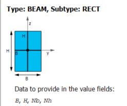
When you create a rectangular section, the width, b and height, h are along the beam element co-ordinate system y and z respectively (as shown in image below).
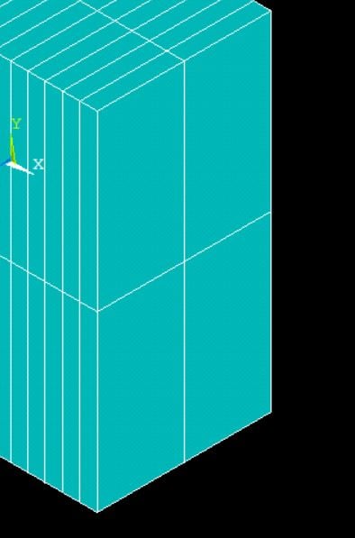
You can turn on the ESYS Element coordinate sys under Plot Controls --> Symbols (with element shape turned off, i.e. /eshape,0) to see how the element coordinate systems are oriented and verify that the b and h are in the respective y and z directions of this esys.
Preferred method would be to use Orientation node/keypoint. Please have a look at the beam188 documentation in ANSYS help here for further information.
Also, this youtube video might help.
Best regards,
Rohith