-
-
August 8, 2017 at 7:59 pm
kwl8rs
SubscriberI am modeling additional variable (AV) flow in a turbulent flume but have run into the problem of significant dissipation of the AV before it reaches the developed turbulent section of the flume. The velocity profile can be seen in the attached image and analyzing the AV concentration as a result of advection is the primary goal, so this poses a problem. I was hoping someone could give me advice on creating an internal inlet to release the additional variable inside the geometry rather than at the face inlet the water enters from. This would allow the additional variable to immediately interact with the turbulent environment rather than only encountering a developed boundary layer after 5 seconds of dissipiation. I've tried doing this by creating a plane inside the geometry, sketching a circular inlet, splitting it from the plane and making it a named selection, but the face split is superimposed onto the outer face of the flume where the initial water inlet is. Do you know of any way to create an internal inlet within a geometry?
Another idea someone told me is that water from the outlet can be used for the inlet, which would allow for a turbulent environment to be present in the entire plume through recirculation. Again I'm not sure if this can be done or what steps to take. Any advice would be appreciated.
-
August 10, 2017 at 7:41 pm
Vishal Ganore
Ansys EmployeeHi, could you please share some snapshots of geometry after creating circular inlet just to understand what is happening exactly?
-
August 14, 2017 at 1:12 am
kwl8rs
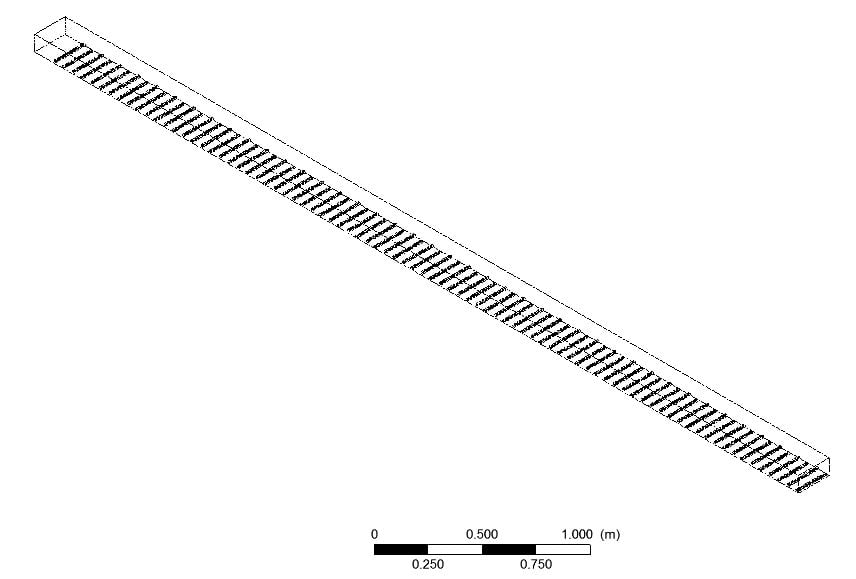
SubscriberI attached a few images of the geometry, additional variable concentration, and velocity field to get a feel for the project.
 entire geometry with inlet on upper left and outlet at bottom right
 geometry showing inlet and roughness blocks to create realistic turbulence
 Additional Variable in XY plane along centerline
 velocity field: you can see turbulence takes time to develop, so inserting the additional variable in the middle of the plume would create the most realistic model. I'm increasing the size of the domain to prevent the additional variable hitting the roof as well.
Thanks a lot for your help!
-
August 30, 2017 at 11:13 am
Holger Grotjans
Ansys EmployeeHi, did you consider to create a local source in the domain? So instead of an inlet you can create the AV at the required location by a source term.
-
August 30, 2017 at 2:35 pm
kwl8rs
SubscriberDo you mean a sub-domain, point source, or source term? I'm using CFX so I'm not sure if I can create a source term.
Thanks for your help!
-
September 4, 2017 at 7:34 pm
Holger Grotjans
Ansys EmployeeWell, sure you can easily create a source term in CFX. Just look at the documentation. For your application you can specify a domain source term specified by a CEL-function, making use of the step-function, to limit the source term to a specific region in the domain.
See section 17.4.1.2.2 in the CFX-Pre Users Guide.
-
- The topic ‘Creating an internal inlet within a geometry or using outlet velocity turbulence profile for inlet’ is closed to new replies.


-
4597
-
1495
-
1386
-
1209
-
1021

© 2025 Copyright ANSYS, Inc. All rights reserved.


