TAGGED: #acp-#compositematerials
-
-
April 10, 2024 at 4:01 am
Aryadipta Nayak
SubscriberHow to create a frustum in ansys acp? The thickness of each layer is 0.2mm with dia (200, 40)
-
April 11, 2024 at 11:53 am
Avnish Pandey
Ansys EmployeeHi Aryadipta,
To create a frustum or a tapered shape in Ansys Composite PrepPost (ACP), you would typically start by defining the geometry of the frustum in a tool like Ansys SpaceClaim or DesignModeler. Once you have the geometry, you can import it into ACP for further processing, such as defining the composite layup.
-
April 11, 2024 at 1:05 pm
Aryadipta Nayak
SubscriberHi Avnish, thanks for reply I need to know do I define the geometry completely or part wise like I need to create 8 layers and each layer of frustum thickness is 0.2. The dia 200mm and 40mm. So I create a revolve geometry with a thin feature taking 1.6 as vertical length and 100mm and 20mm as horizontal dimension. Is it right? Please clarify me if I am wrong
-
April 11, 2024 at 7:25 pm
Avnish Pandey
Ansys EmployeeHi Aryadipta,
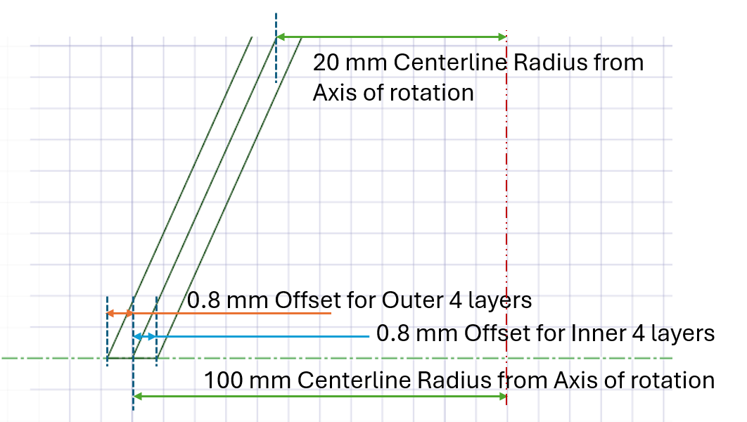
The diameters should basically lie in the midsurface of the frustum. You can offset on either side by 0.8 mm for 4 layers as shown in the figure.
You can form 4 partitions of 0.2 mm each on either side of the midline to give you 8 layers as required. Followed by revolution of the 8 surfaces so formed, about the axis of rotation.
Hope this helps.
-
April 13, 2024 at 11:48 am
Aryadipta Nayak
SubscriberAnd also how to add layers in acp pre setup
Hi Avnish, created the surface body in design modeller please clarify me about the rosette selection and OSS for the frustum.
-
April 16, 2024 at 2:05 am
Aryadipta Nayak
SubscriberHi Avnish unable to draw the geometry, having issues on creating the mid surface in design modeler, please help me out
-
- The topic ‘Creating a frustum’ is closed to new replies.


-
3477
-
1057
-
1051
-
940
-
912

© 2025 Copyright ANSYS, Inc. All rights reserved.


