TAGGED: fluent, iso-surface, post-processing
-
-
April 18, 2024 at 2:12 am
Dato
SubscriberHi,
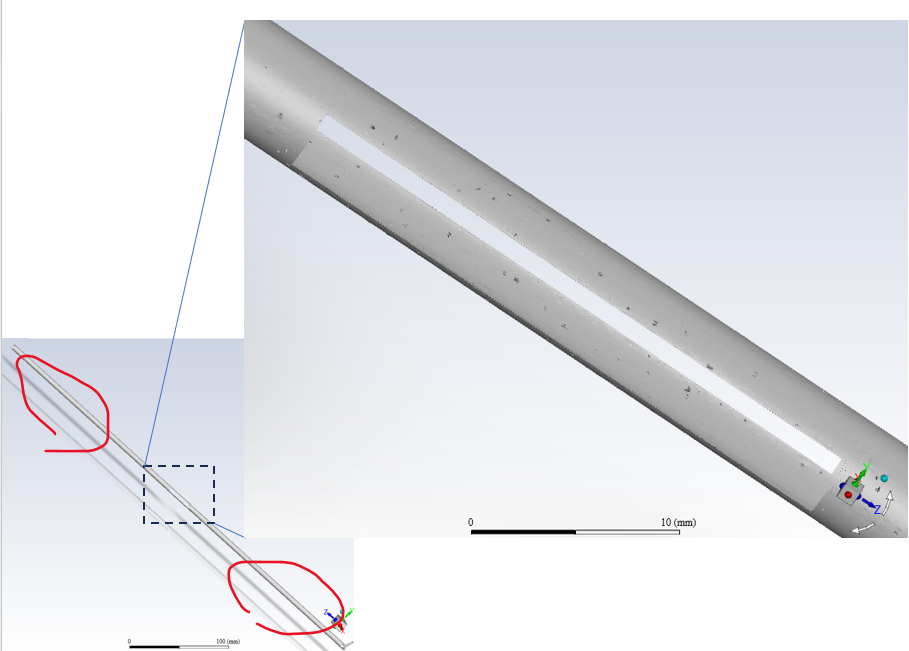
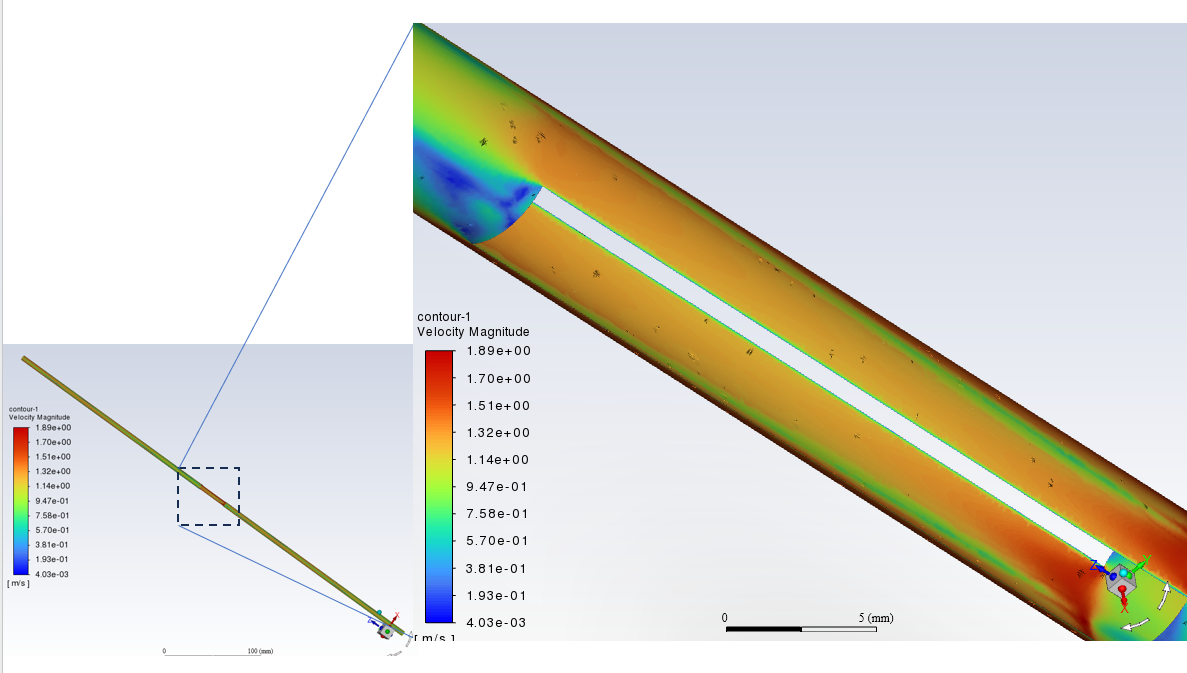
I have used iso-surface using expression and quadric surface to created side surface of a cylinder. But both created surfaces are not that smooth in the middle and appears many black and grey spots as shown below. It's weirder that the spots only occur in the middle while both side of surface circled in red are smooth. And it is middle region that what I want to visualize.
Both side surfaces created in two ways have same problems and it have influenced contour display.
I want to know how to resolve this problem or I have no choice but to turn to tecplot the like. I prefer Fluent to do post processing .
Any suggestions is appreciated.
Best regard.
-
April 18, 2024 at 9:41 am
CFD_Friend
Ansys EmployeeHi Lee,
This might be due to the display option.
Use the Display Options dialog box to enable lighting effects. Lights On is enabled by default with the Automatic lighting method. The Automatic lighting method automatically selects the best lighting method for the current display in the graphics window. You may disable Lights On or select an alternate method from the Lighting drop-down list. Flat is the most basic method: there is no interpolation within the individual polygonal facets. Gouraud and Phong have smoother gradations of color because they interpolate on each facet.
-
April 18, 2024 at 11:57 am
Dato
SubscriberHi dear CFD_Friend,
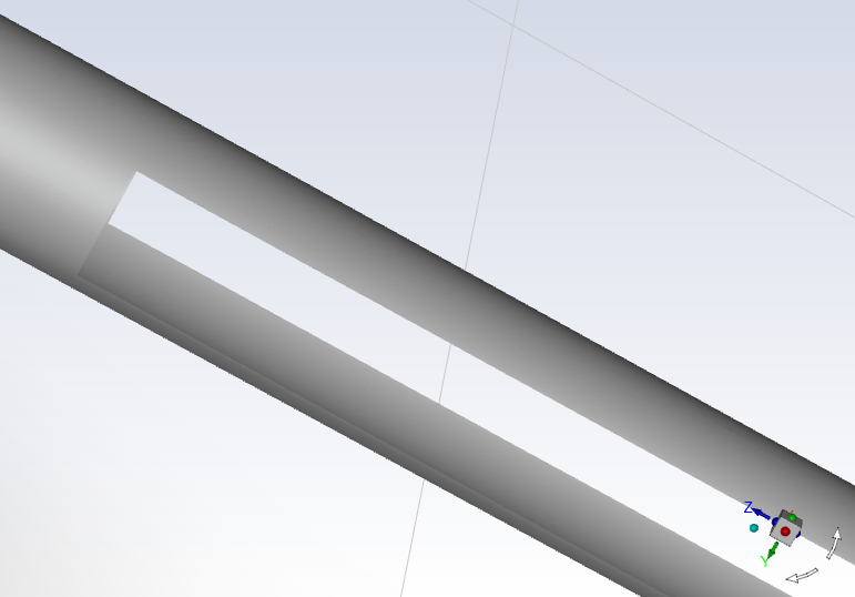
It's even strange that after I restarted Fluent and read same case, data and created same surfaces, I found side surface created by quadric become smooth but the one created by expression is still spotted. This one shown below is creted by quadric.
I have tried gouraud, flat, phong and any other panels in View but it don't help????. Thanks for your reply.
-
-
- The topic ‘Created surfaces in Fluent are not smooth with spots’ is closed to new replies.


-
3467
-
1057
-
1051
-
929
-
896

© 2025 Copyright ANSYS, Inc. All rights reserved.


