We’re putting the final touches on our new badges platform. Badge issuance remains temporarily paused, but all completions are being recorded and will be fulfilled once the platform is live. Thank you for your patience.
General Mechanical

General Mechanical

Topics related to Mechanical Enterprise, Motion, Additive Print and more.

Create an autofrettage analysis with residual stresses used as initial condition

    • 201182080
      Subscriber

      Hi Everyone

      I'm working on an analysis that requires residual stresses created from an autofrettage process.

      I've seen how it is recommended to using multiple steps instead of linking two static structural analysis.

      So i've simulated the autofrettage part just to feel what kind of results to expect.

      Created 2 steps. step 0-1: ramp the load at 1.5 x the materials yield streng; step 1-2 remove the load so that it is 0MPa at step 2. analysed the results.

      Created another sim with 4 steps, adding on the previous sim, step 2-3: zero load; and step 3-4 326MPa (maximum pressure that the component will be subjected to in real life).

      In real life, the pressure is loaded by cordinates (x & y) where it varies with x. I feel like I'm messing up somewhere because i'm not getting the results i though i would. Not sure how two pressure loads (step 1) loads the pressure using steps but load pressure 2 (intended to be step 2) using tabular data can meet.

      please help, for masters.

      variable pressure not appearing under analysis settings


    • peteroznewman
      Subscriber

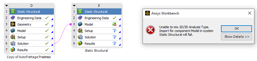
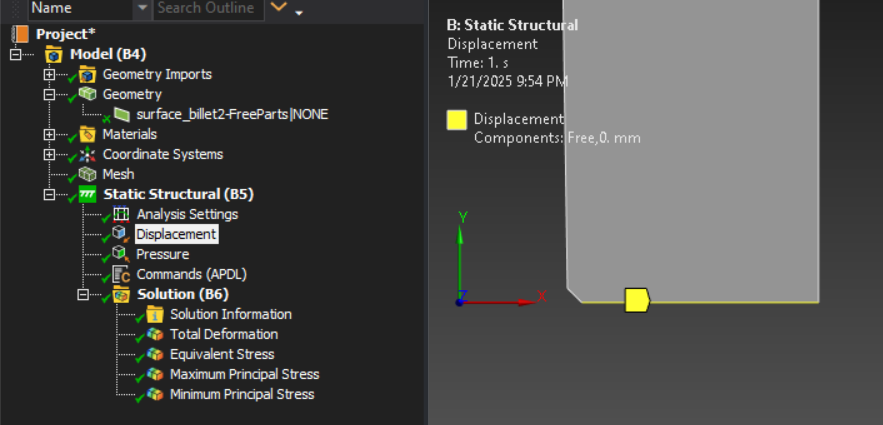
      Looking at your geometry and loads, this looks like a perfectly axisymmetric problem and I created an axisymmetric analysis to answer your question. The benefits of axisymmetric analysis are: boundary conditions are simpler, the solution is faster, and output results for normal stress and strain are in terms of radial (X), axial (Y) and hoop (Z) components. To build an axisymmetric model, open the CAD system you used and align the barrel axis to the Y axis. Slice the solid at the XY plane.  Create a surface at the cut face on the +X side of the Y axis and delete the solids. Start a new Static Strucural and import the geometry then right click on the Geometry cell and select Properties. In the Properties window, on row 13, set the Analysis Type to 2D.  You must do this before you open the Model cell.  Open the Model, click on the Geometry branch and in the Details window, set the 2D Behavior to Axisymmetric. The boundary condition is to select the bottom edge that represents an end face of the barrel and set a Displacement of Y=0 leaving X free to have radial expansion.

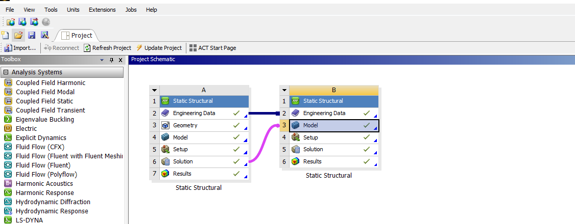
      I don’t know how to use Tabular Data with an Independent Variable of Y (in the axisymmetric model) as Step 3 of a multistep single analysis. There may be a way using APDL tables and if there are, perhaps someone will reply with that information.  Instead I used two analyses and used the INISTATE command to write out the state of stress and strain after the autofrettage pressure had been applied and removed in a two-step first analysis, then used the INISTATE command to read that state into a second analysis to apply the working pressure load in step 1.  See ANSYS Help for more information on INISTATE.

      I used an Aluminum material with the following properties. Note I have a plasticity material model which is required for a residual stress problem.

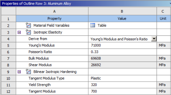
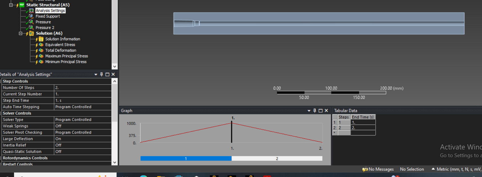
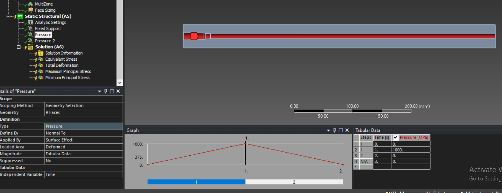
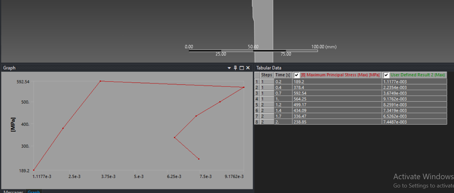
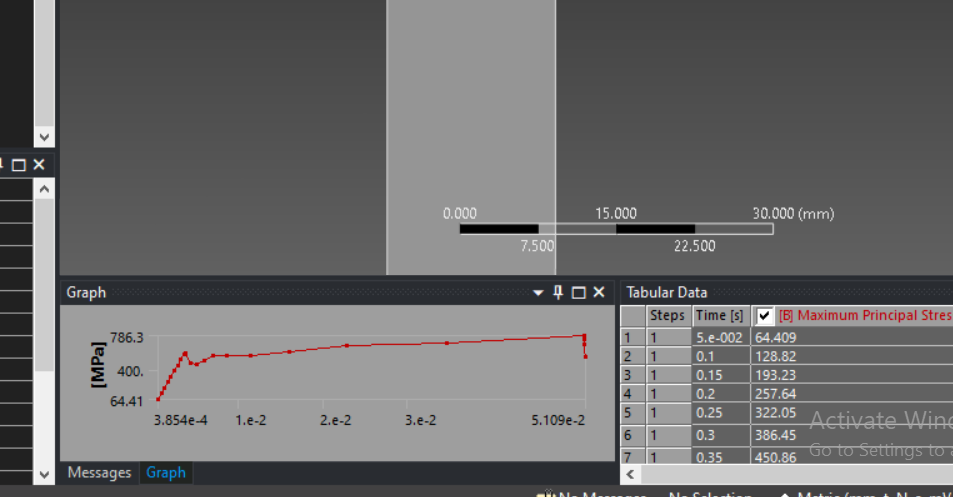
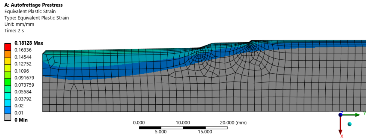
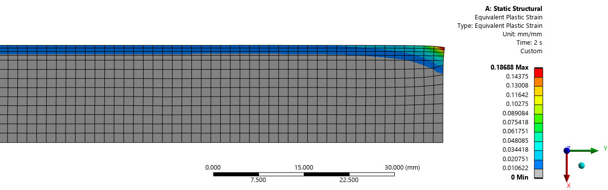
      In analysis A, the internal pressure ramps up to 150 MPa in step 1 and ramps down to 0 in step 2. The equivalent plastic strain on the inner surface is 3.4% for the 150 MPa internal uniform pressure. Note that 100 MPa of uniform pressure does not create any plastic strain in analysis A.

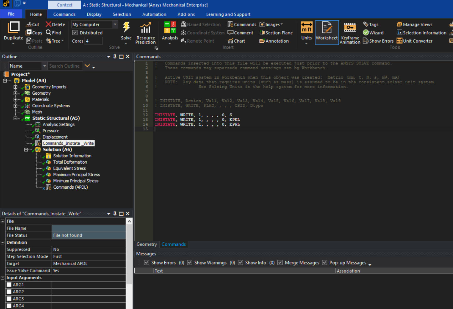
      There are two Command objects in analysis A, the first under Static Strucural writes the state of stress, the elastic strain and the plastic strain at the end of step 2 to file.ist.

      INISTATE, WRITE, 1, , , , 0, S
      INISTATE, WRITE, 1, , , , 0, EPEL
      INISTATE, WRITE, 1, , , , 0, EPPL

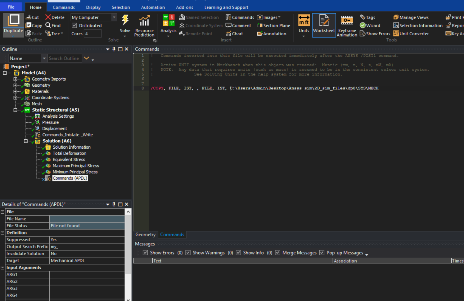
      The second Command object is under the Solution branch and copies the file up a couple of levels in the folder structure.

      /COPY, file, ist, , file, ist, ..\..\

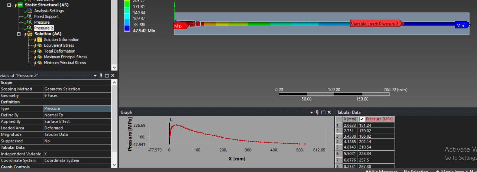
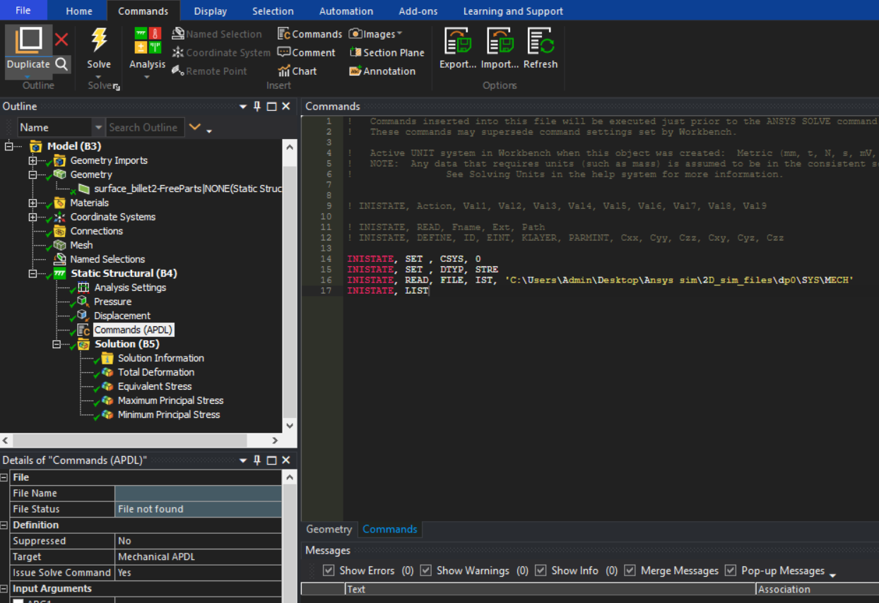
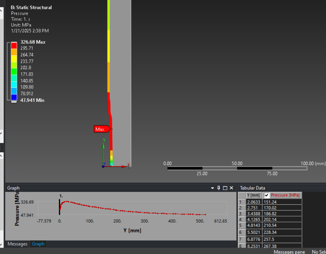
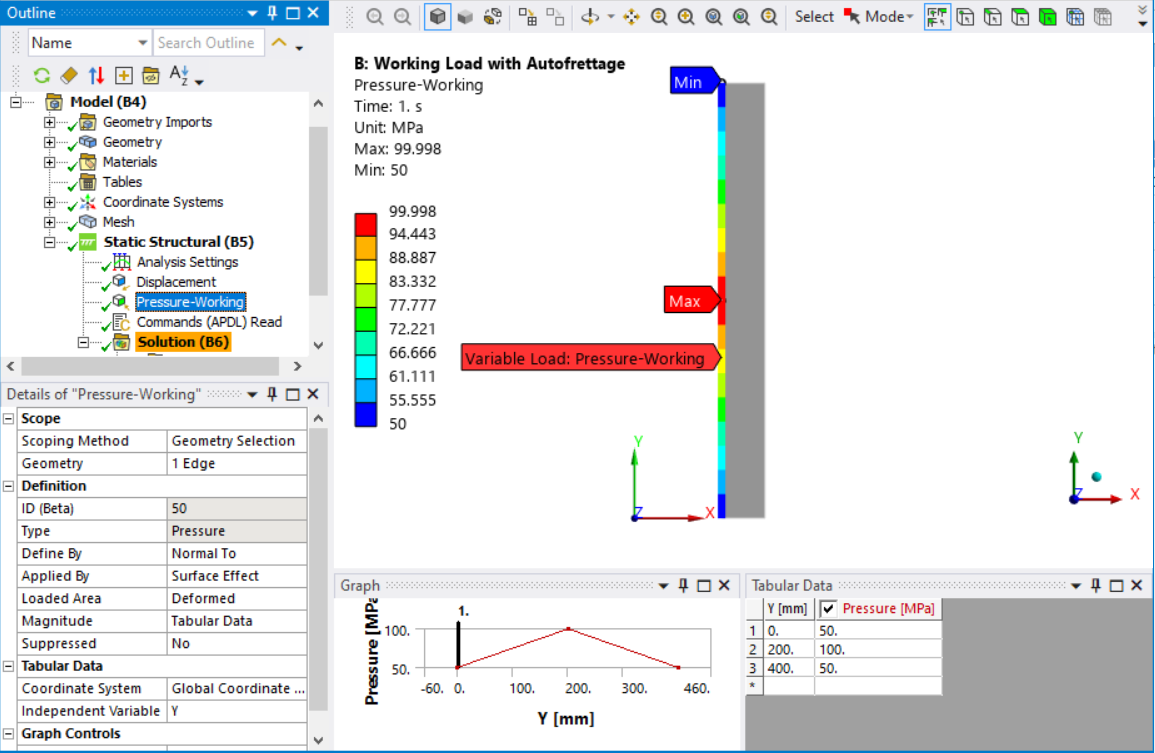
      In analysis B, I created a “working” pressure load as a fuction of the Y axis. 

      The Command object under Static Structural has the following command:

      /COPY, file, ist, ..\..\, file, ist
      INISTATE, READ, file, ist

      I found these commands in this reference.

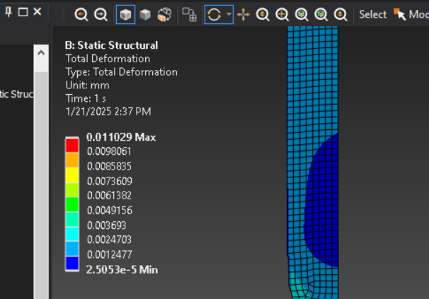
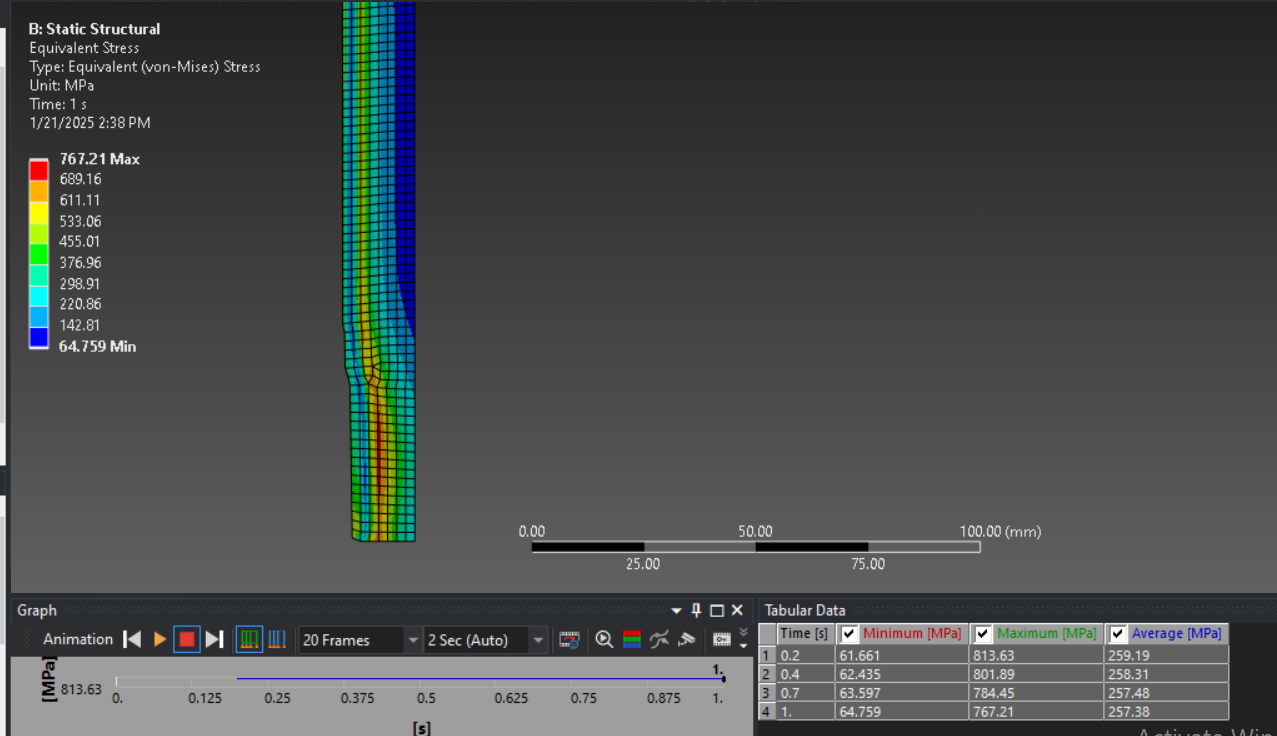
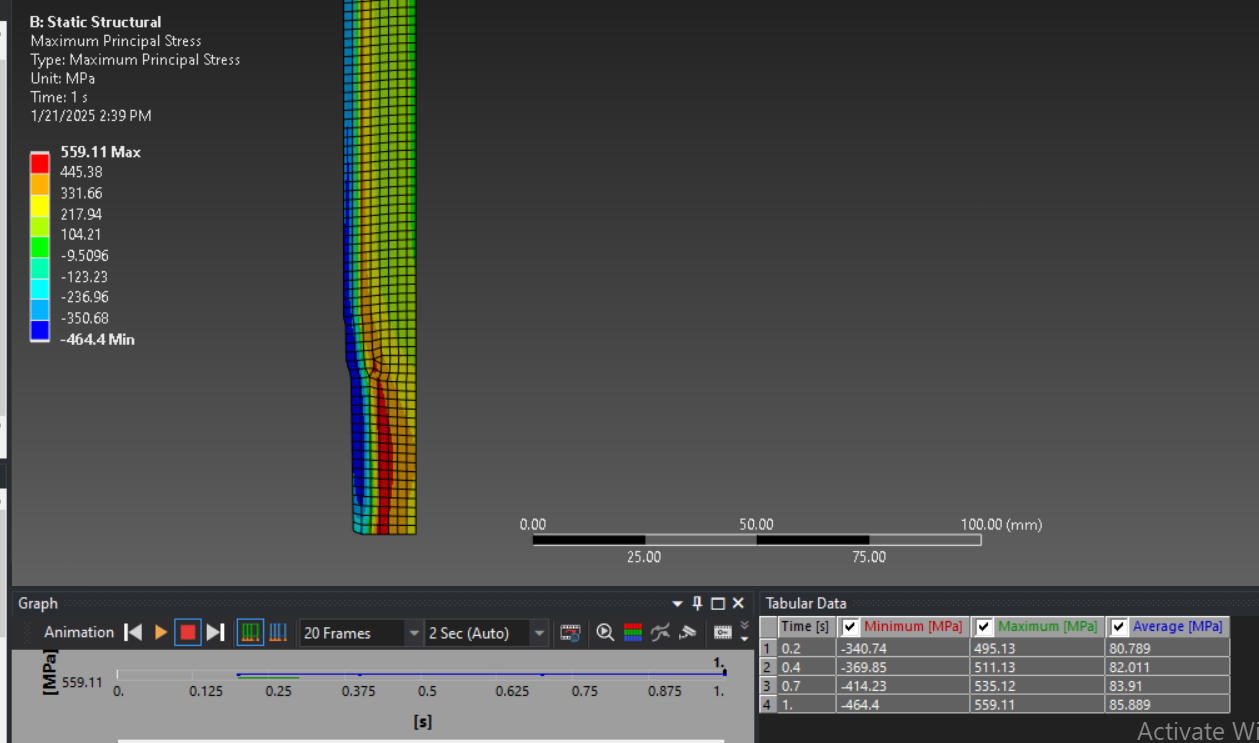
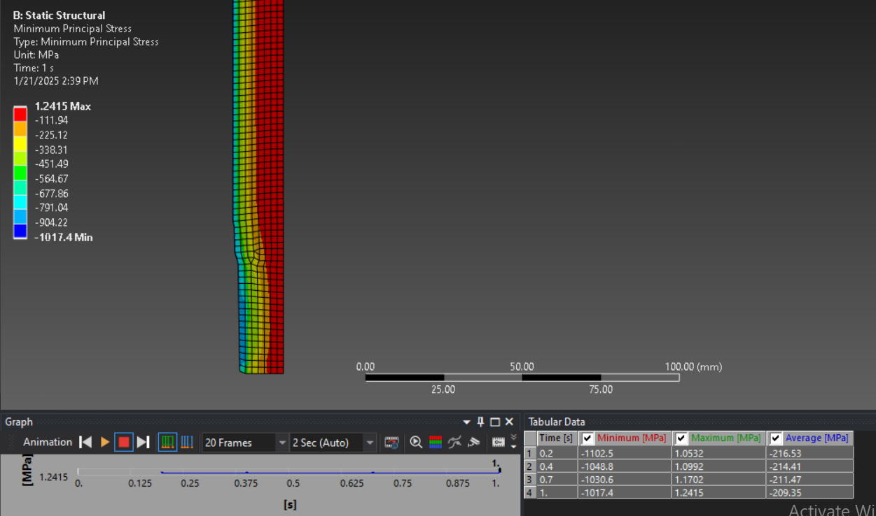
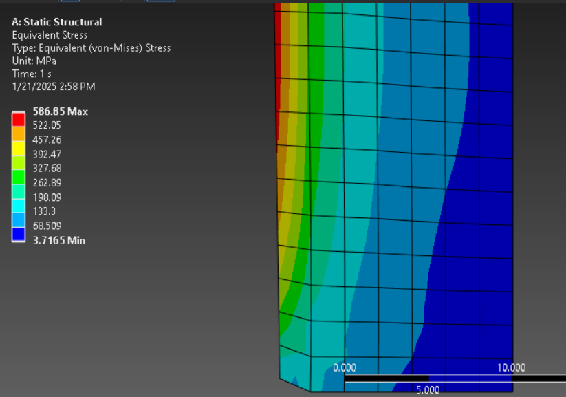
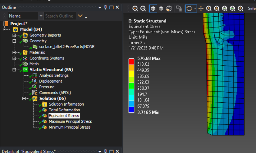
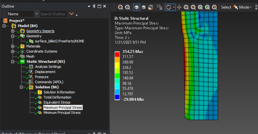
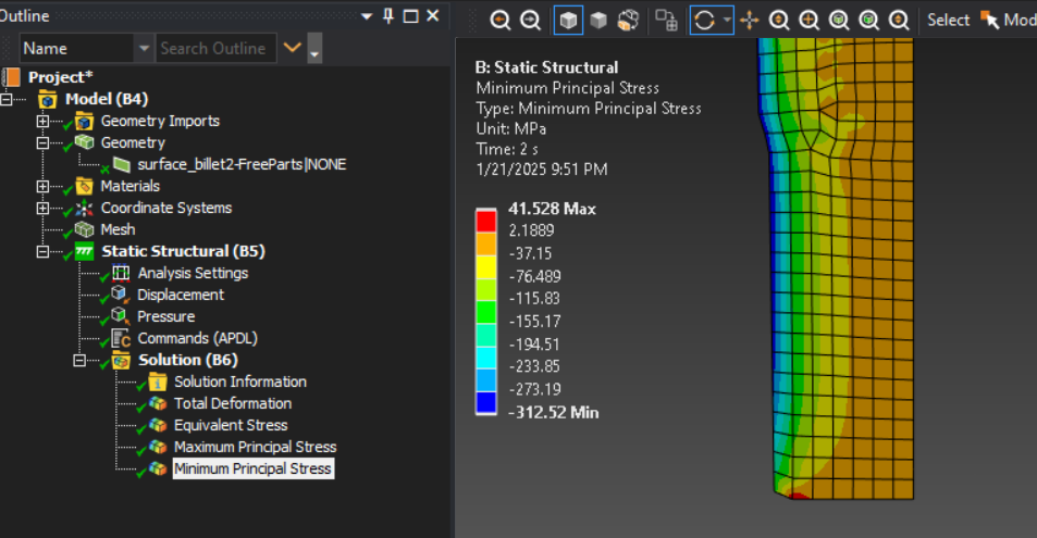
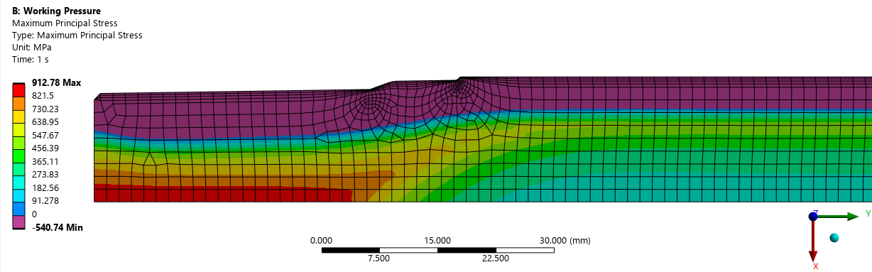
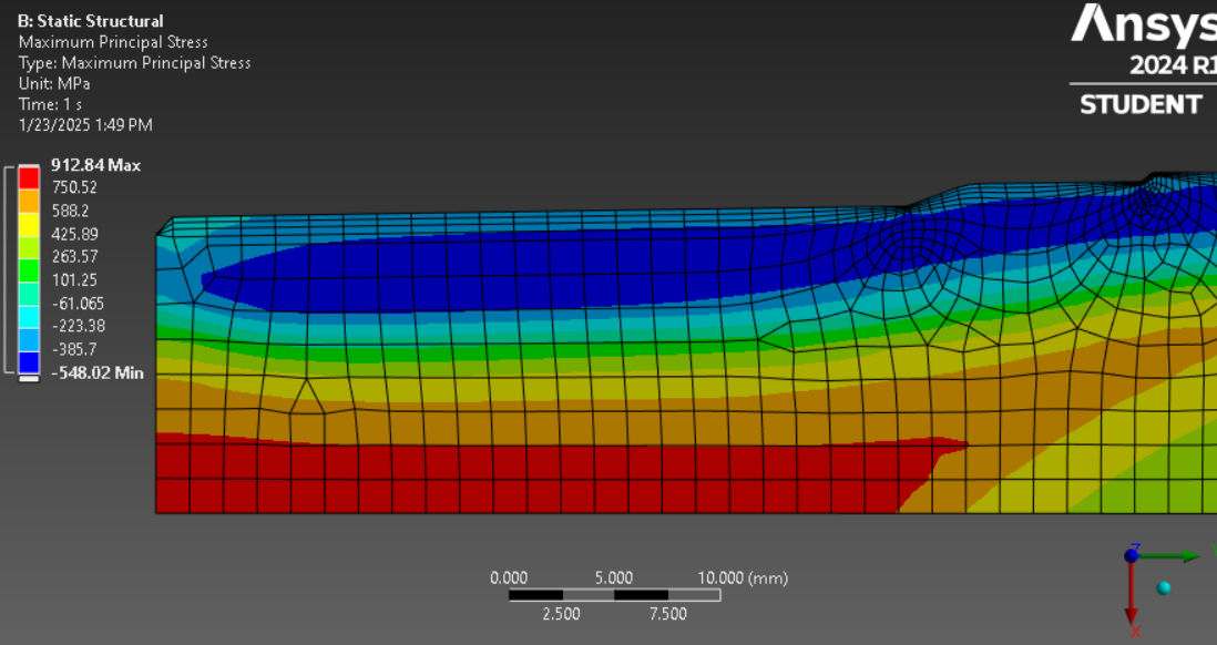
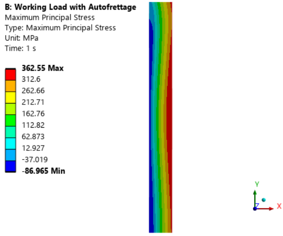
      Below are some images of the stress at the working pressure load using the initial state from analysis A.

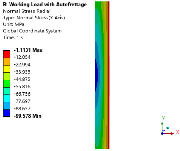
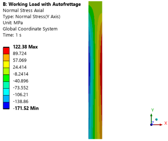
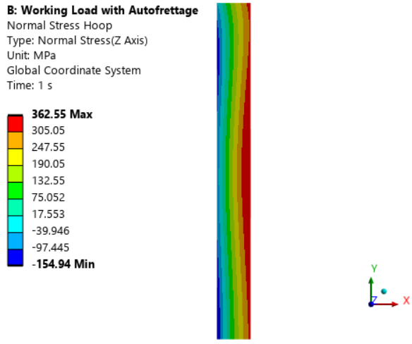
      Note that the inner wall (left edge) is all compressive stress in the Max Principal plot.  This is what prevents fatigue cracking.

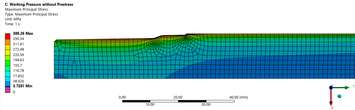
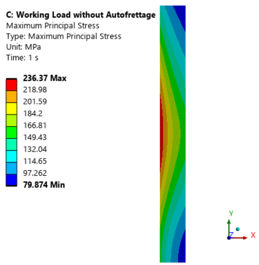
      Contrast the last plot with the stress from that same working pressure if there was no residual stress from the initial treatment of the autofrettage pressure. Notice that the inner face is all tensile stress which is a risk for fatigue cracking.

    • 201182080
      Subscriber

      May I first take the opportunity to appreciate the efforts you have taken to explaining how to tackling the problem.
      Your guidance coupled with this video

      ?si=LYpy05eRdGRWxRb9, has painted a clear path that i need to follow.

      I guess it is not as clear cut using 2 step approach to solving this problem, especial if the loads differ with the independent variable. One has to split the simulations.

      I'll start first with appreciating the information on "inistate" and learning how to use it as it is something new to me.
      May I please have the next 24 Hours (or less) to develop everything as per your guidance and provide feedback?

      The next step post this, is using the autofrettgaed component (Analysis A) for a coupled static structural and thermal analysis (analysis B and/or C).

      Simulating the coupled load inputs (thermal and pressure that both vary along the path) that act simultaneously on the component.

      Something that will be interesting to observe.

      Thank you once again. Let me try this approach and provide feedback.

    • 201182080
      Subscriber

      Hi again

      I'm back, I have a question after trying this. Why does the solver work when the surface has a Y axis. It had an error when i initially tried to model it with the x-axis.

      When i try the method with your command guidance, it fails to load in analysis B:

      Command to write

      above is how i typed out the command.

      I had to suppress the above, not sure what i was doing wrong here.

      I from here on I tried to use the method in the video (link shared above). Linking the stats like this.

      Reading from file, ist (above). Then doing the normal setup up before solving.

      total deformation, seems very low, not sure if I'm in the ball park 🧐

      Above is the the variable pressure with the y being the independent variable


      Without autofrettage🤔

      Figure is lower than when i had initially modeled with the axis in the x-axis. I wonder why. I previously got 706MPa as the maximum Von Mises stress.


      Just thought i should give feedback as to how things went.

    • peteroznewman
      Subscriber

      Thanks for a detailed reply!

      Why does the solver work when the surface has a Y axis? It had an error when i initially tried to model it with the x-axis.

      Ansys structural developers arbitrarily chose the Y axis as the axis of revolution.  All the code assumes that. If you prepare geometry using the X axis by mistake, the code is still going to revolve the geometry you provide around the Y axis and you will solve a completely different model to the one you think you are getting and the answers will be completely wrong, so there is no point in comparing those results with results for geometry that has the axis of revolution on the Y axis.

      I used the example code I found in the reference. I suggest you use the /COPY function exactly as I show until you get a working model.  That works without the linkage between Solution and Model.

      I dragged a Static Structural out to make analysis E then I dragged the Solution cell from D (a duplicate of A) and dropped it on the Model cell of E. This created the following error message, even if I set the Geometry property of analysis E to 2D before the drag and drop.

      I'm using ANSYS 2025 R1.  I recommend you use two unlinked Static Structural models with 2D Analysis Type on the Geometry cells and get the INISTATE write and read files to transfer data from the autofrettage prestress model to the working pressure model.

      Which edge has the Displacement BC X = Free, Y = 0?  I guess you used to top edge because on the bottom left corner, that node is moving in the Y direction. That may be correct if that is the free surface of the barrel.  You don’t want both the top and bottom edges to be constrained, just one is correct.

    • 201182080
      Subscriber

      Hi again

      That is very interesting to know. Makes me wonder if i can still use Ansys for a simulation where the component is heated and allowed to deform due to gravity.

      The left corner is a chamfer. it is not loaded. I used the bottom of the component (edge closer to the chamfer).

      So when using the copy function, i shouldn't create a directory to where the solver information is created?

      I must keep it to "..\..\"?. Before copying "E:" directory into the command, I had used yours as is but failed to load information. Maybe I must run through all my steps again.

    • peteroznewman
      Subscriber

      Reread my previous reply because I was editing it as you wrote the reply above.

    • peteroznewman
      Subscriber

      If gravity is acting along the Y axis, that is an axisymmetric load so you can do that in an axisymmetric model. 

      If a temperature load is symmetic around the axis of rotation, then you can do that in an axisymmetric model.

      Imagine you have a problem where the barrel was horizontal and the sun was heating up the top side of the barrel and not the bottom side. Assuming that gravity creates a non-negligable deformation, then even though the geometry is axisymmetric, the loads are not and you would need to do a 3D model to correctly simulate those loads. In that case, there is no need to orient the barrel along the Y axis. In your case, since the barrel is so thick, I expect the effect of the gravity load would be negligible.

      • 201182080
        Subscriber

        Heat influx will be assumed to be symmetrical as it will be generated from the center of the component.

        coupled heat and pressure loads to determine how many cyclic loads can be loaded before failure.

        Sun idiology was good.

    • peteroznewman
      Subscriber

      So when using the copy function, i shouldn't create a directory to where the solver information is created?

      I must keep it to "..\..\"?. Before copying "E:" directory into the command, I had used yours as is but failed to load information. Maybe I must run through all my steps again.

      The benefit of using    ..\..\     is that it always works, even if you copy the Workbench project to another folder or drive because it is a relative address.

      If you edit the command in the Solution branch, I found I had to right click on the Solution and Clear Generated Data to get the edited command to be used.

      • 201182080
        Subscriber

        Good information. Thank you so much

    • 201182080
      Subscriber

      I'm just appreciating this engagement so much. and i appreciate all the efforts you're putting in to guiding me.

      Most people throw information and disengage. I appreciate all your efforsts.

      I was able to get the setup to run with all the inistate commands provided above.

      Please see below the difference in results from the inistate command you shared vs the one i used from the attached link:

      above is the constraint on the bottom edge

      such a big difference in the results from both inistate commands

    • peteroznewman
      Subscriber

      Did you plot the plastic strain in analysis A at the end of the autofrettage pressure load to show that the barrel had exceeded the yield strength and developed some residual stress?

      • 201182080
        Subscriber

        This is my EPEL1 and EPPL1 below.

        What is concerning is that it doesn't even reach the yield limit (750MPa). I'll double check my tangent modulus value.


        I did a bit of hand calculations for a thick wall pressure vessel. Taking the part of the component where the outer diameter and the inner diameter are parallel. Thickness t/D is > 0.05. Created a 2D sheet of that part of the barrel and subjected it to a pressure value and measured the results. The only hand calculation that comes close to the measured simmulation results is the hoop stress.


    • peteroznewman
      Subscriber

      You could change the pressure in step 1 of analysis A to higher values until you get a good amount of plastic strain. Make a contour plot to see how far that goes through the wall thickness.  If you set the pressure too high, the simulation will fail to converge.

      If you save a .wbpz archive file using File, Archive in Workbench and upload that file to a file sharing site such as Google drive or OneDrive or Jumpshare and post a link to that file in your reply, I will take a look at your model.

    • 201182080
      Subscriber

      Hi again

      Wow that is so kind of you.

      Please see attached link: https://drive.google.com/file/d/1fPaeyHpFIH_Q7TuAJBI8isRTkhGQ2OKR/view?usp=sharing

      I did change the pressure to a higher one almost 1.5 x the yield limit.

      please see updated stress-strain curve:

    • peteroznewman
      Subscriber
      1. Analysis Settings, Large Deflection = On for both analysis A and B.
      2. Mesh Element size = 1.6 mm and the settings shown below to improve fidelity of the mesh to the geometry.
      3. Use an Inflation mesh control like this:
      4. With those changes, there is between 1 and 2% plastic strain along the length of the barrel in analysis A.
      5. It looks like a small chamfer would be helpful at the other end, but in reality, there would be a cap or connectior on the end to apply the pressure.
      6. Under a the working pressure, notice that the entire length of the inside surface of the barrel is in a state of compressive stress. Note that this is a one step analysis, not a two step.
      7. Duplicate analysis B and in analysis C, suppress the Commands (APDL) object and solve. Notice that the inner surface of the barrel is in tension.
      8. Additional note: When I did the same mesh controls on both A and B, I got a different mesh!  I wanted the mesh to be identical, so I deleted A and duplicated B so that I had the identical mesh in both systems.  INISTATE can map between different shaped meshes, but I didn’t want to get into that.
    • 201182080
      Subscriber

      Hi again

      1. I had initially did the simulations with large deformation being on, I got a warning message that "large deformation effects are active which may have invalidated some of your applied supports...." so I ended up switching it off as I was unsure if this negatively affects the quality of the results.
      2. From point 2-9 I was able to update the details as guided and got a max plastic strain of 0.1895.
      3. From point 10-13 i got similar resulst:
      4. Ok noted on point 14. May one day you'll get into it😀. I've enjoyed learning from you and was able to pin point my shortfalls and where to improve. It has really been an insightful learning process.
      5. I'd like to reiterate my appreciation, you honestly went the extra mile on this one, I'm truly grateful. I really enjoyed learning new things. I believe that the model and setup has matured a lot from where it was initially, especially being able to link the solution as initial state in the next analysis. Thank you so much.
    • 201182080
      Subscriber

      Hi again

      Just wanted to know. A periodic forcing function and a fatigue analysis, would they have the same end result?

      I'm seeing something on hysteresis, so I'm following that trail.

      I'm asking this because on a post in 2018 titled "How can I apply Cyclic loading in ANSYS?" you asked about periodic forcing function.

      Without assisting as I'd like to follow the trail and potentially present the work if i got stuck, I wanted to hear if there are topics you think I can follow.
      I'm trying to go through chapter 6 on Cyclic loading analysis. To evaluate the components behaviour from repeated loading of the same varying pressure. Then perform the fatigue analysis to determine how many loads before failure. On fatigue failure, there are a lot of material online, so i think on that one I'll be great.

    • peteroznewman
      Subscriber

      For a periodic forcing function, you can do a static structural analysis of one period to obtain the peak stress amplitude in the structure.  The duration of the period will tell you how many cycles occur per hour and it is cycles that are counted in fatigue analysis.

      If you have that, you can look up the stress amplitude on the SN curve and obtain the cycles to failure.  Then you can convert that to hours of exposure to the periodic forcing function.

      The challenge is finding the SN curve for your material. 

      You should also do a Modal analysis to know what the resonance frequencies are in your structure.  If the frequencies in the periodic forcing function are close to any resonant frequencies, then the effect on the structure will be dynamic and not static.  If the first mode of the structure is an order of magnitude higher than the frequency in the periodic forcing function, then the effect on the structure can be evaluated in a static analysis.

      • 201182080
        Subscriber

        Thank you so much for the advise. Let me dive into this.
        Thank you so much once again.

      • 201182080
        Subscriber

        Basically, the variable load pressure (x vs y) has to be converted into a sin (x), cos (x), or tan (x) so that the information on applitude is extracted.
        Yeah the Sn curve for these materials I'm studying are not public knowledge, making the study hard.
        But we learn.


Viewing 16 reply threads
  • You must be logged in to reply to this topic.