Ansys Assistant will be unavailable on the Learning Forum starting January 30. An upgraded version is coming soon. We apologize for any inconvenience and appreciate your patience. Stay tuned for updates.
Fluids

Fluids

Topics related to Fluent, CFX, Turbogrid and more.

Could not access to the momentum option in the boundary condition

    • aalawi
      Subscriber
      I am simulating the thermal management of a battery pack consisting of 8 cylindrical batteries with constant heat generation. Horizontal fins are attached to the batteries for cooling, and the system is subjected to forced air convection.
      Problem Description:
      I am encountering an issue when defining the boundary conditions for the fin surfaces.
      1. Limited BC Options: When I select the wall surfaces of the fins, the boundary condition menu does not allow me to access the Momentum tab to define the wall motion. Only the Thermal tab is available. This prevents me from explicitly verifying and setting the wall to a "No-Slip" condition.
      2. Incorrect Velocity at Walls: As a result of the above, when I run the simulation, I observe non-zero velocity values at the fin surfaces in the post-processing results. This is physically incorrect, as these solid walls should have a no-slip condition (velocity = 0 m/s), which is skewing my results.
      Could you please help me identify why the momentum boundary condition options are disabled for these wall surfaces and advise on how to correctly enforce the no-slip condition?
      Thank you for your time and assistance.
    • B D
      Ansys Employee

      Hello, 

      1. If you are running a CHT simulation, you will not see the momentum option for the surfaces associated with solid domain. Please ensure that you are selecting the surfaces of the fluid domain side.
      2. Fluent by default, has no-slip BC applied for the walls. Hence, even if you do not provide it manually, it should be No-slip for the surfaces with wall BC. Please ensure you have activated the Boundary values option while displaying the contour.


      • aalawi
        Subscriber

        Hello There,

        Thank you for your support.

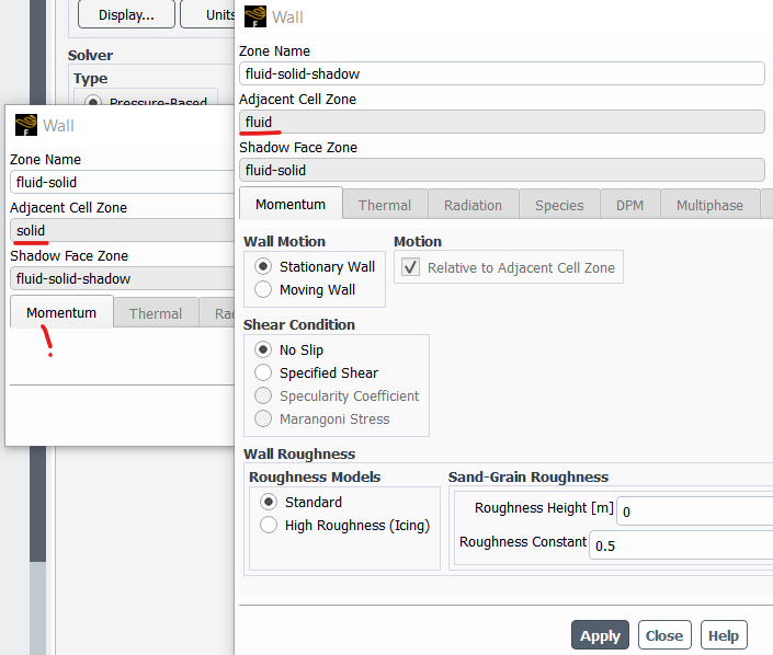
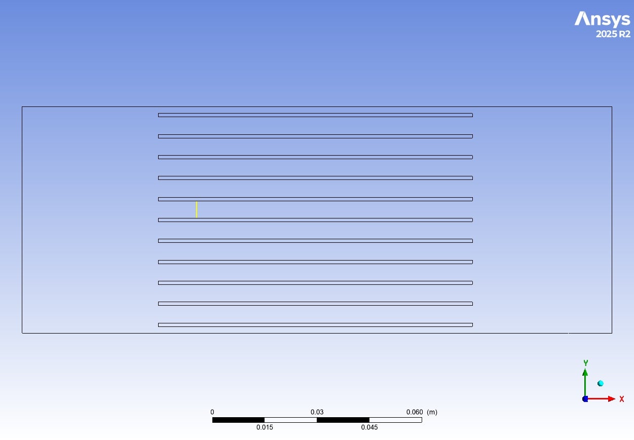
        Please if you can elaborate more about point 1? You mean I should select the surfaces of the fluid domian, like in my case I defined the fluid domian as a box and I used boolean so I can make an interface between the fins and the flow domain. So should I define the walls of the fins from the fluid side not the fins side?

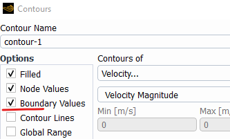
        Also, I understand that by default ansys defined them No-slip but what I want to define roughness for the fins, how could I do that?

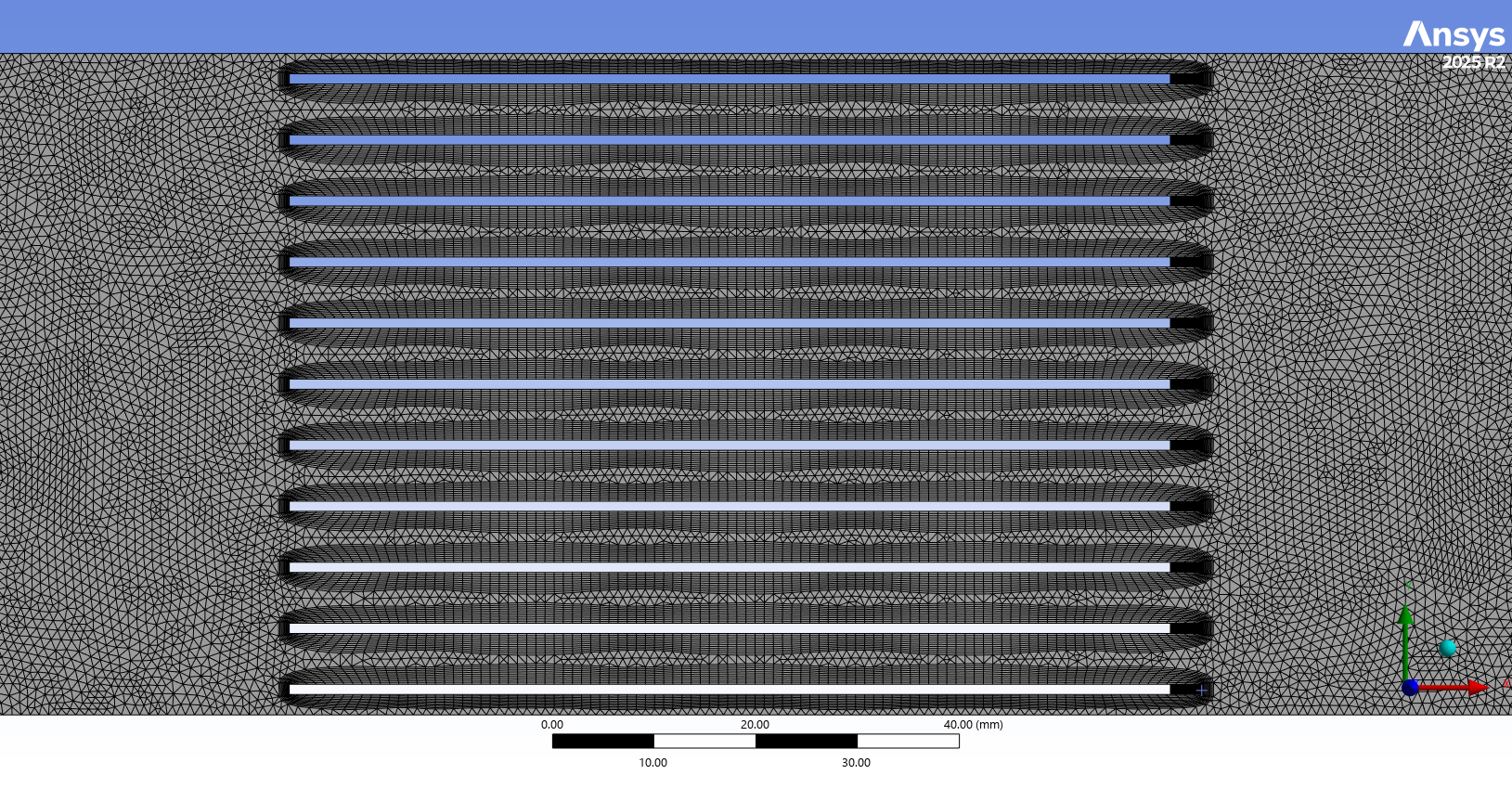
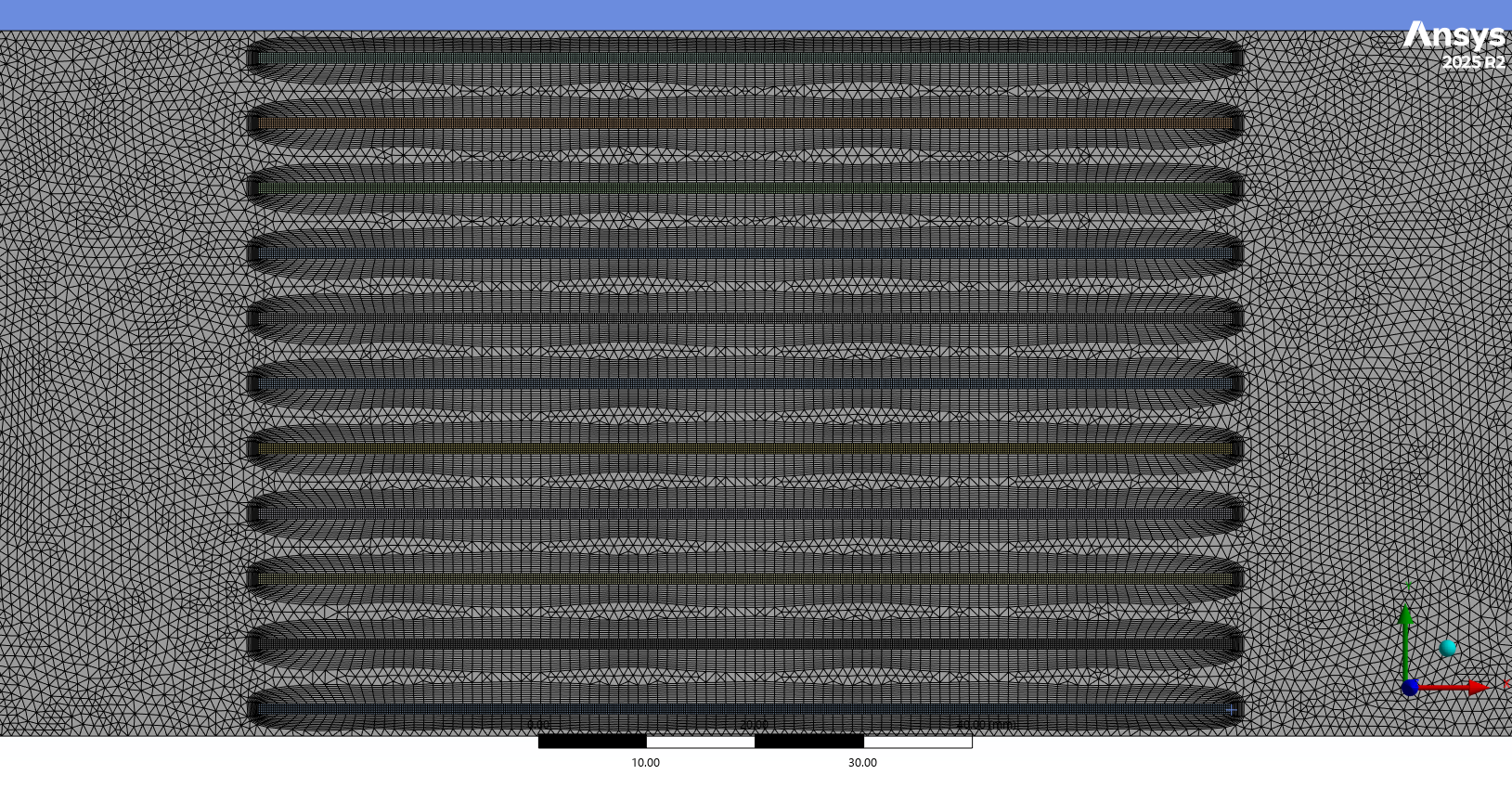
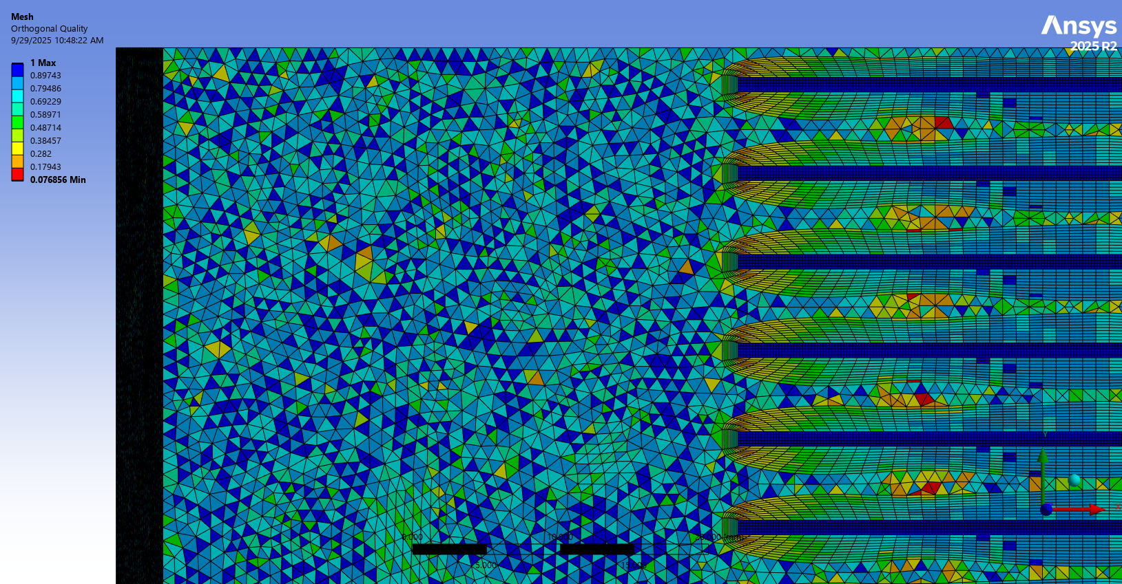
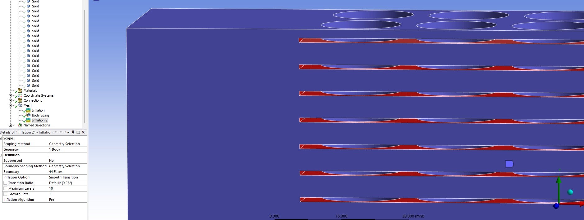
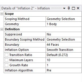
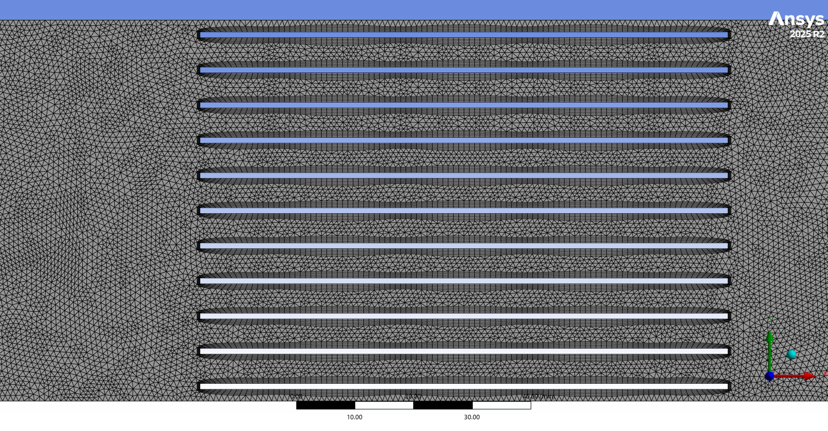
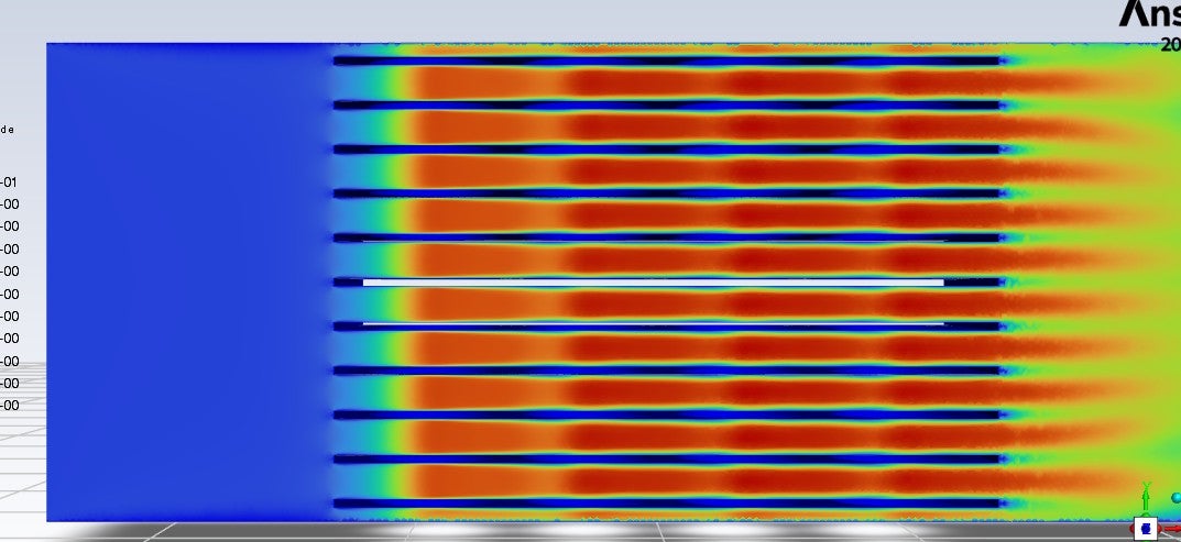
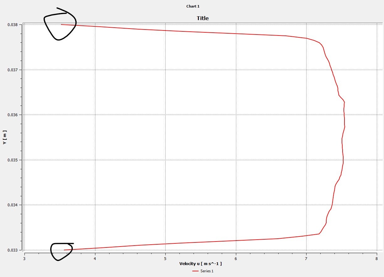
        I tried to use inflation, for simple case I got the velocity at the surface of fin is zero but becuase I have pack , the inflation was so messy becuase fins are close to each other and still could not reach zero velocity at the fin surfaces, please if you can help with this matter that would be much appreciated.

        Thank you in advance.

    • B D
      Ansys Employee

      The interface is made of two sides, the side attached to the fluid domain and the side attached to the solid domain. The solid side of this interface will not have the momentum BC, but the fluid side will have. In the image below, the walls are two sides of the interface.

      Even without wall roughness, no-slip gives you zero velocity on the wall. Make sure you have good quality mesh and case is converged.

    • aalawi
      Subscriber

      Hello

      Thamk you for your expliantion

      I have another question about calculating the average Nu for the 4 cells. Should I do it like in the attached photo, where the net value is the average? Or is there another way to calculate the average Nu for the whole pack?

      Thank you for your support.

    • aalawi
      Subscriber

      Hello

      I hope you are doing well.

      Regarding to fins and battery, I have attached here photos of my mesh, I tried to use the inflation around the fins surfaces (For the fluid domain) so the intensity of the mesh is increased, leading to accurate capturing of the boundary layer and the gradients. However, I think the quality is not much good also, the inflation has a bad distribution, as you can see. In addition, the velocity still not zero at the fin surfaces.

      Please if you can guide me what is the best way to do the mesh for the domain considering the computational time and the accuracy of the solution.

      Thank you in advance.


    • B D
      Ansys Employee

      Hello,

      You shouldn't need as many boundary layers. Please go with 3-5 layers to begin with.

      Would you mind sharing the snip of velocity contour where you see non-zero velocities with how you are creating them?


    • aalawi
      Subscriber

      Hello,

      Thank you so much for your responding, I really appreciate your support.

      I have attached here the photos for the contour of the velocity, also I tried to plot the velocity from the fins surfaces to see exactly if the velocity zero or not and as you can see still there are many regions the velocity is not zero at them. 

      However, there are some regions when I plot the velocity between two fins (Surfaces of the fins), the velocity approcahes zero. 

      Please if you can guide me how can I fix this issues.

      Thank you.


    • B D
      Ansys Employee

      I don't see any issue with the contour. The flow between fins will have non-zero velocities.

      To plot velocity only on Fin surfaces, provide a name selection for just fins and use them to create contour. From what I can see in contour, the fin surfaces have zero velocities on them, but it is hard to say as you have displayed vel on other faces too.

    • aalawi
      Subscriber

      Hello

      I hope you are doing well.

      Thank for your support.

      I attacehd here the photos of the velocity profile between the fins surfaces as you can see ( I plot the velocity profile for that line), the velocity was not zero.

      I used an inflation layer for 3 layers and as you can see when I plot the velocity was not zero

      How can I avoid this kind of issues?

    • Rob
      Forum Moderator

      That's a CFD Post plot that maps the Fluent cell data onto the nodes (CFD Post comes from CFX and is node rather than being cell based). Replot in Fluent. However, whilst the wall velocity is zero the near wall cell velocity may not be zero.

      If you refine the mesh a lot more you may eventually see the near wall cell with near enough no velocity but it's unlikely to make much difference to the results whilst increasing the compute overhead. However, I'd be more concerned about the pulsing effect in the flow caused by your mesh. 

    • aalawi
      Subscriber

      Hello,

      I hope you're doing well. 

      Thank you for your continued support. I'm writing to ask how to calculate the mass flow rate for each internal branch of a pipe system, as shown in the attached photos. These branches are internal channels machined inside a cold plate. The design was created in SolidWorks, and these internal branches were not individually named during the modeling process. The photos provide a detailed look at the geometry for your reference.

      Could you guide me about how can I calculate the mass flow rate for this case?

      Thank you so much.


    • B D
      Ansys Employee

      You can create the required surfaces where the mass-flow is to be caculated (say cross section of pipe) into independent CAD session with same coordinates as geometry in your case file (example: if the mass-flow is to be measured at (0,0,0) with plane normal (1,0,0), create the surface in CAD tool with same details), export these surfaces as stl files and then import them in Fluent case using Surface > Create > "Imprint" option. This imprinted surface can then be used into Fluent for post-processing purposes. Please refer user manual for more details on this feature.

    • Rob
      Forum Moderator

      To add, this has been answered a few times, and the Search Forum tool can be very useful! 

Viewing 12 reply threads
  • You must be logged in to reply to this topic.
[bingo_chatbox]