-
-
April 26, 2024 at 3:24 pm
YEEUN KO
Subscriber"The attached photo includes the inductor design, core loss, and input current waveform. The input current is defined as {abs(20sin(2pi60time))+(abs(5sin(2pi50000time))-2.5)}. However, I think the core loss is too high. Core information such as the B-H Curve and B-P Curve has been provided. Can anyone help with this issue? I'm not sure if this waveform is correct."
-
May 3, 2024 at 3:08 am
HDLI
Ansys EmployeeHello YEEUN,
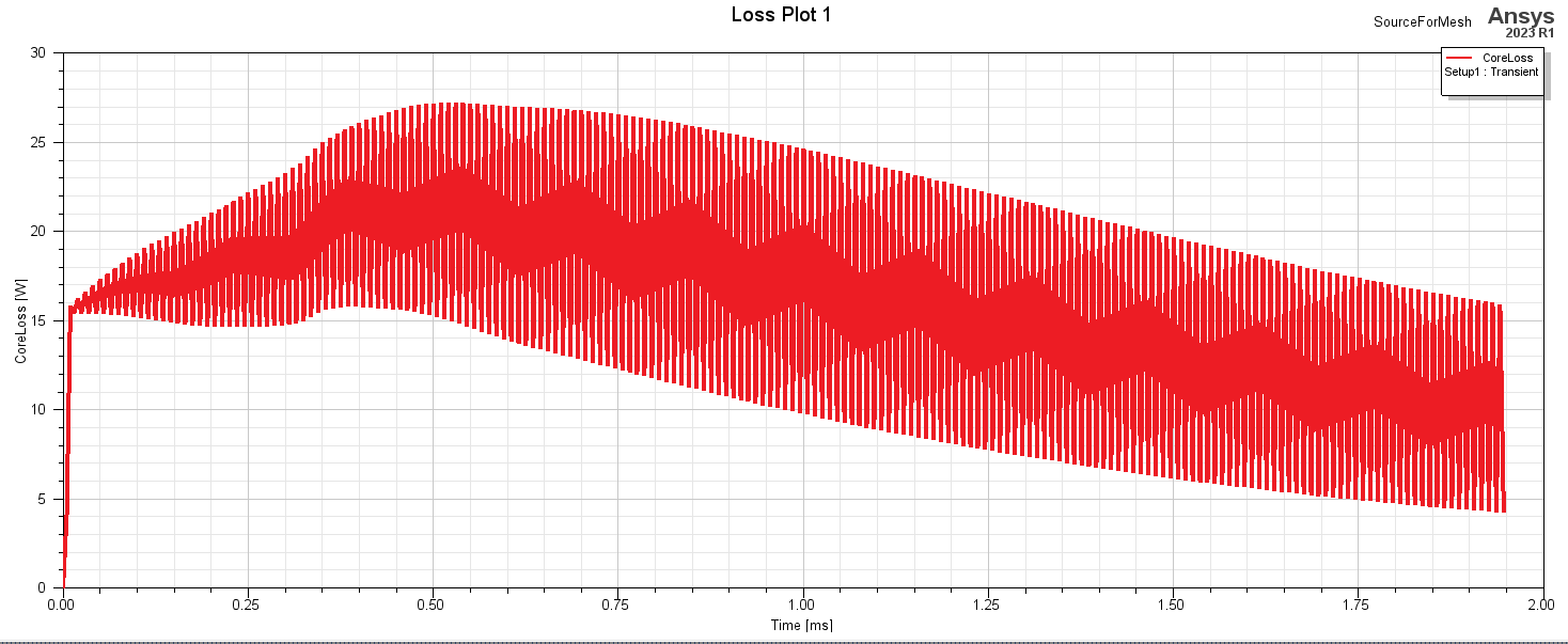
   Maxwell would use dynamic core loss model in time domain, so it is not in steady state in beginning of simualtion and the core loss results may have calculation tolerance.
   Could you enter more cycles of 0 current to reach steady state, then increase current ?
   In 24R1, user could specify custom core loss. Could you try this too?
HDLI
-
June 3, 2024 at 5:27 am
YEEUN KO
SubscriberSo you mean we have to wait a while to get to the normal state? Then I put the sine wave rectified from above as input, and if I do this, I get the core loss value of the transient section, not the core loss value of the normal state?
-
-
- The topic ‘Core loss Analysis _ transient’ is closed to new replies.
-
3407
-
1057
-
1051
-
896
-
882
© 2025 Copyright ANSYS, Inc. All rights reserved.