Ansys Assistant will be unavailable on the Learning Forum starting January 30. An upgraded version is coming soon. We apologize for any inconvenience and appreciate your patience. Stay tuned for updates.
Fluids

Fluids

Topics related to Fluent, CFX, Turbogrid and more.

Core Annular Flow (CAF) VOF model

    • Zakizam
      Subscriber

      I'm working on CFDs from Core Annular Flow. Oil is designed to flow in the core and water will be annular. I use the VOF model and the k-e turbulent, then I set oil as primary phase, water as secondary. The oil inlet is in the small pipe section and the water inlet is in the big pipe.

      The problem is why the flow fails, the fluid flow is dominated by oil along the pipe and water is only found at the inlet and outlet ends?

      The attached images are Pipe Meshing, Oil Vol. Fraction, and Water Vol. FractionMeshing, Oil Vol. Fraction, Water Vol. Fraction

    • DrAmine
      Ansys Employee

      Can you please provide information and I hope you are not running steady. The water at outlet might be ignored as it is due to reversal flow.

    • Zakizam
      Subscriber

      Thank you for your kind response Mr. Aben, this is my final project for graduation, it is very important to me to succeed in this project.


      This is my settings, hope you can solve the problem.


      File :https://drive.google.com/file/d/1t4AVI-BihagXWbKfJ5kei3xYWxu8nN_O/view?usp=sharing


      Best Regards,


      Zaki

    • DrAmine
      Ansys Employee

      Please insert any relevant information here.

    • Zakizam
      Subscriber

      Do you mean the fluent settings like this sir?


      v  Setup (General)


      §  Solver


      ·       Type                            : Pressure Based


      ·       Time                           : Transient


      ·       Gravity                        : Y: -9.81 m/s2


      ·       Velocity Formulation : absolute


      v  Multiphase Model (VOF)


      §  Number of Eulerian Phases: 2


      §  Implicit Body Force


      §  Vol. Fraction Parameter Options


      ¨     Formulation          : Explicit


      ¨     Vol. Fract. Cutoff : 1e-06


      ¨     Courant Number   : 0.25


      §  Phases


      ·       Oil       : Primary Phases


      ·       Water  : Secondar Phases


      §  Phases Interation


      ·       Surface Tension


      ¨     Model                                            : Continuum Surface Force


      ¨     Surface Tension Coefficient         : 0.05 n/m


      v  Viscous Model


      §  Model                                : k-epsilon (2eqn)


      §  K-pesilon model               : Standard


      §  Near-Wall Treatment       : Enhanced Wall Treatment


      v  Materials


      §  Oil


      ·       Density                        : 960 kg/m3


      ·       Viscosity                     : 0.2 kg/ms


      §  Water


      ·       Density                        : 998.2 kg/m3


      ·       Viscosity                     : 0.001003 kg/ms


      §  Steel


      ·       Density                        : 8030 kg/m3


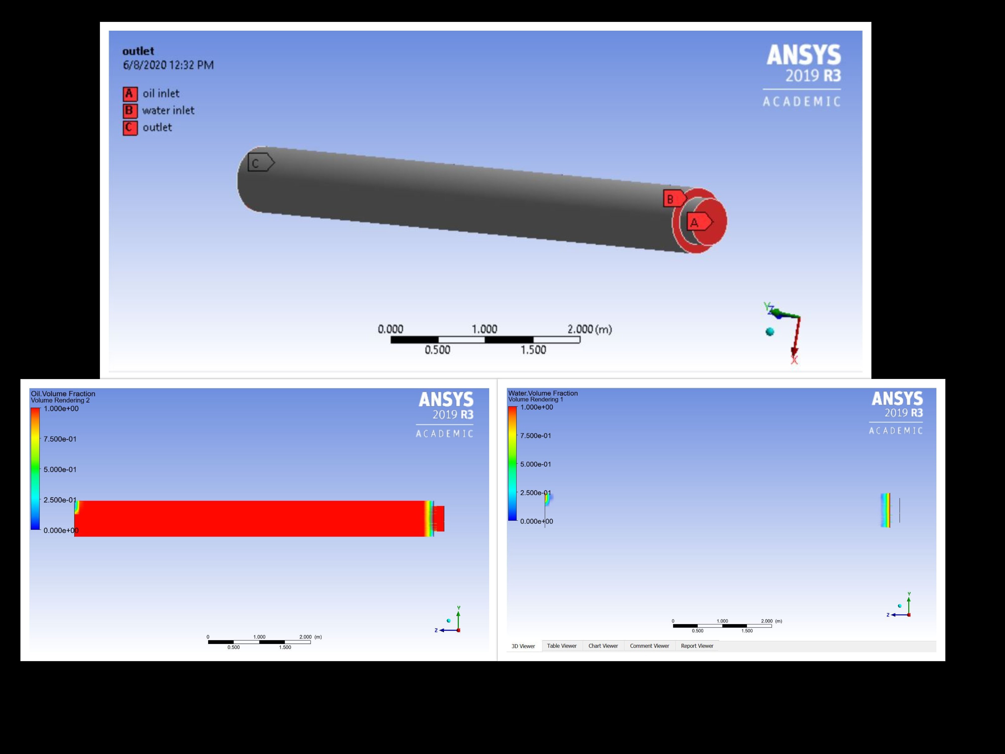
      v  Boundary Conditions


      §  Oil Inlet   


      ·       Velocity Specification Method           : Magnitude, normal to boundary


      ·       Velocity Magnitude                            : 0.53 m/s


      ·       Initial Gauge Pressure                         : 0 Pa


      ·       Turbulence


      ¨     Specification Method                   : Intensity and Viscosity Ratio


      ¨     Turbulent Intensity                       : 5%


      ¨     Turbulent Viscoisty Ratio             : 10


      §  Water Inlet           


      ·       Volume Fraction                                 : 1


      ·       Velocity Specification Method           : Magnitude, normal to boundary


      ·       Velocity Magnitude                            : 0.3 m/s


      ·       Initial Gauge Pressure                         : 0 Pa


      ·       Turbulence


      ¨     Specification Method                   : Intensity and Viscosity Ratio


      ¨     Turbulent Intensity                       : 5%


      ¨     Turbulent Viscoisty Ratio             : 10


      §  Outlet


      ·       Phase   : Mixture


      ·       Backflow Direction Specification Method     : Normal to boundary


      ·       Backflow Pressure Specification                   : Total Pressure


      ·       Gauge Pressure                                               : 0 Pa


      ·       Pressure Profile Multiplier                             : 1


      ·       Turbulence


      ¨     Specification Method                               : Intensity and Viscosity Ratio


      ¨     Turbulent Intensity                                   : 5%


      ¨     Turbulent Viscoisty Ratio                        : 10


      §  Wall


      ·       Wall Motion                           : Stationary Wall


      ·       Shear Condition                      : No Slip


      v  Solution


      Ø  Solution Methods


      §  Pressure-Velocity Coupling


      ·       Scheme                                               : PISO


      ·       Skewness Correction                          :1


      ·       Neighbor Correction                           :1


      ·       Skewness-Neighbor Coupling            : Enabled


      §  Spatial Discretization


      ·       Gradient          : Least Squares Cell Based


      ·       Pressure           : PRESTO!


      ·       Momentum     : First Order Upwind


      ·       Turbulent Kinetic Energy       : First Order Upwind


      ·       Turbulent Dissipation Rate     : First Order Upwind


      ·       Transient Formulation            : First Order Implicit


      §  Initialization Methods


      ·       Hybrid Initialization


      ¨     Patch         : Water, Value (1)


      §  Run Calculation


      ·       Parameters


      ¨     Number of Time Steps      : 100


      ¨     Time Step Size (s)            : 0.001


      ¨     Max Iteration                    : 20


      ¨     Reporting Interval            : 1


      ¨     Profile Update Interval     : 1

    • Zakizam
      Subscriber

      Hope this reference will describe my project


      Niazi, S. (2018). CFD Simulation of a Crude Oil Transport Pipeline : Effect of Water. Petroleum & Petrochemical Engineering Journal, 2(6), 4–8.


      Numerical simulation of heavy oil flows in pipes using the core-annular flow technique K. C. O. Crivelaro1, Y. T. Damacena1, T. H. F. Andrade2, A. G. B. Lima1 & S. R. Farias Neto2

    • DrAmine
      Ansys Employee

      How long did you run the case? Zero Pascal at outlet is actually wrong and will depend on the reference density you are setting. What is expected at outlet? A churn flow or separated flow?

    • DrAmine
      Ansys Employee

      Or use outflow ( I do not like that boundary condition type).

    • Zakizam
      Subscriber

      the calculation takes about 15-20 minutes. what i am expected is i can see the water or oil volume fraction and pressure drop along pipe length.water vol. faction

    • DrAmine
      Ansys Employee

      Yes I know the paper. So you need to run a for long time. In the paper they are using outflow as outlet boundary condition. You can further contact the authors of the paper.

Viewing 9 reply threads
  • The topic ‘Core Annular Flow (CAF) VOF model’ is closed to new replies.
[bingo_chatbox]