-
-
October 22, 2021 at 1:29 pm
estat
SubscriberIs it possible in Ansys Workbench to assign a coordinate system at each node of an irregular surface, and each z axis of those coordinate systems to point normal to the surface area, depending on where it is located?
October 22, 2021 at 2:18 pmErik Kostson
Ansys Employee
Can you please explain what you want to do, and why you want to do this?
thank you
Erik
October 24, 2021 at 5:44 pmestat
SubscriberHi Eric!
Thank you for your answer once again!
Unfortunately, this time I cannot share information about the project.
What I am interested in, is to assign BC's and loads at nodes, depending on their normal vector with respect to their location on a surface.
I would just like to know if this work can be carried out by Ansys Workbench.
Thank you!
October 24, 2021 at 9:53 pmpeteroznewman
SubscriberWhat you describe sounds like a contact algorithm, which ANSYS does very well. You can have an irregular surface on one body and another body can make frictionless contact where only normal forces are generated at the contact points. Can you imagine how you might use contact to achieve your mysterious goals?
October 27, 2021 at 2:16 pmestat
SubscriberHi Peter!
I sincerely apologise for the delayed answers and for the reduced information I provided! I know that you are doing your best to help!
Actually it is a thermal problem. I have an irregular geometry and I want to assign the anisotropic properties of the material depending on the location of the elements.
Imagine an elipsoidal type of geometry. I want to have a local coordinate systmem at each node and each z axis of this coordinate system to point perpendicularly on the surface of its location.
Thank you for the time that you are devoting!
October 27, 2021 at 2:24 pmErik Kostson
Ansys EmployeeHI
See the nrotat command that rotates the nodal coordinate system as needed. There is though a limit on how many coordinate systems you can define I imagine, so if you have 1 million nodes and need so many coordinate systems .
This post is also useful if you use WB mechanical
Hope this helps
October 27, 2021 at 5:03 pmpeteroznewman
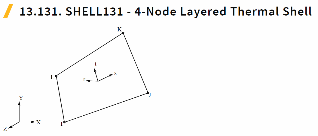
SubscriberEach shell element has an element coordinate system where the s and t vectors are in the plane of the element and the r vector is normal to the element surface. Here is a figure from the Theory Manual.
 If you have a solid mesh for the thermal analysis, Workbench makes it very easy to skin the surface of the solid with shell elements. These will each have their own local normal to the irregular surface.
October 29, 2021 at 7:13 amestat
SubscriberThank you so much for the information provided!
I will check both of your suggestions!
Have a nice day!
Viewing 7 reply threads- The topic ‘Coordinate system at each point of a surface’ is closed to new replies.
Ansys Innovation SpaceTrending discussionsTop Contributors-
3467
-
1057
-
1051
-
929
-
896
Top Rated Tags© 2025 Copyright ANSYS, Inc. All rights reserved.
Ansys does not support the usage of unauthorized Ansys software. Please visit www.ansys.com to obtain an official distribution.
-


Ansys Assistant

Welcome to Ansys Assistant!
An AI-based virtual assistant for active Ansys Academic Customers. Please login using your university issued email address.
Hey there, you are quite inquisitive! You have hit your hourly question limit. Please retry after '10' minutes. For questions, please reach out to ansyslearn@ansys.com.
RETRY


