-
-
August 11, 2021 at 2:43 pm
SV
SubscriberDear Sir/Madam
I am trying to predict the location of shock wave inside a converging- diverging nozzle. My program can see the supersonic flow at the outlet. I expect to see the variation of location of shock wave as I increase the outlet pressure, but as I increase the outlet pressure the program start diverging.
I would like to see the variation of shock wave through nozzle. Please let me know if you can provide help.
Thank you
Saeid Vafaei
August 11, 2021 at 4:13 pmRob
Forum ModeratorPlease post some images so we can see what's going on.
August 11, 2021 at 4:16 pmSV
SubscriberWould you like to send you the files that you can run the code and see the issue
August 11, 2021 at 5:20 pmSV
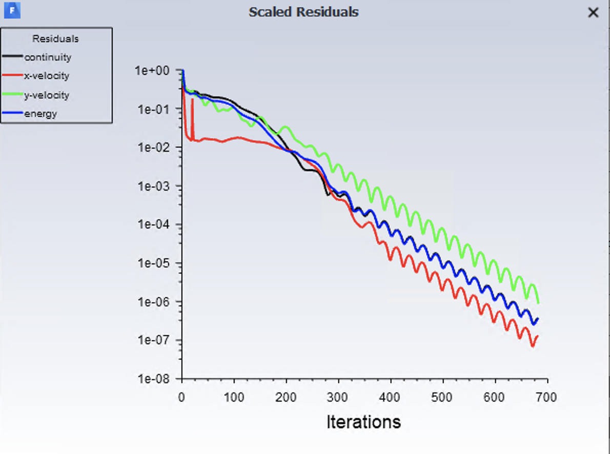
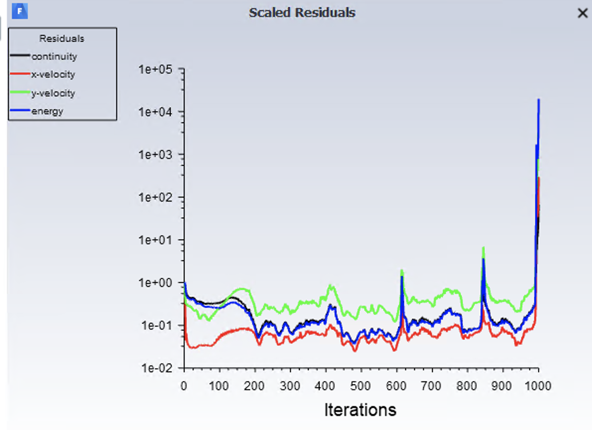
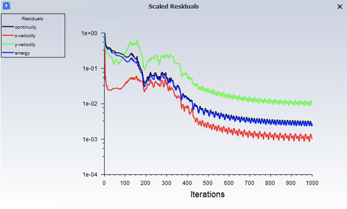
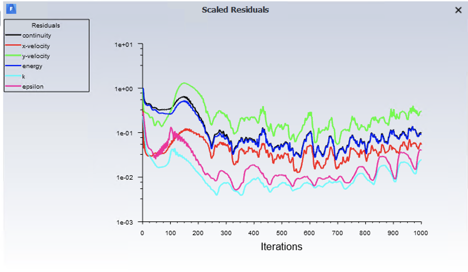
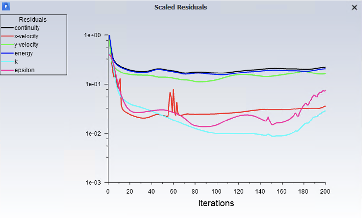
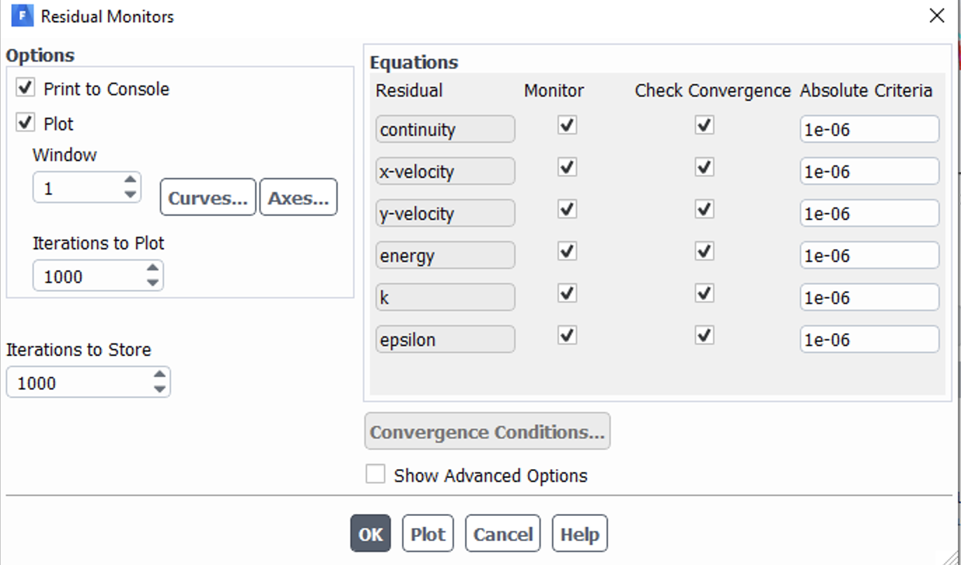
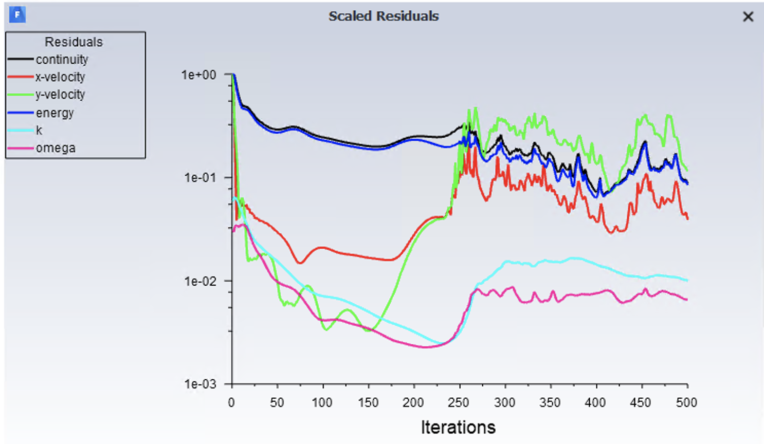
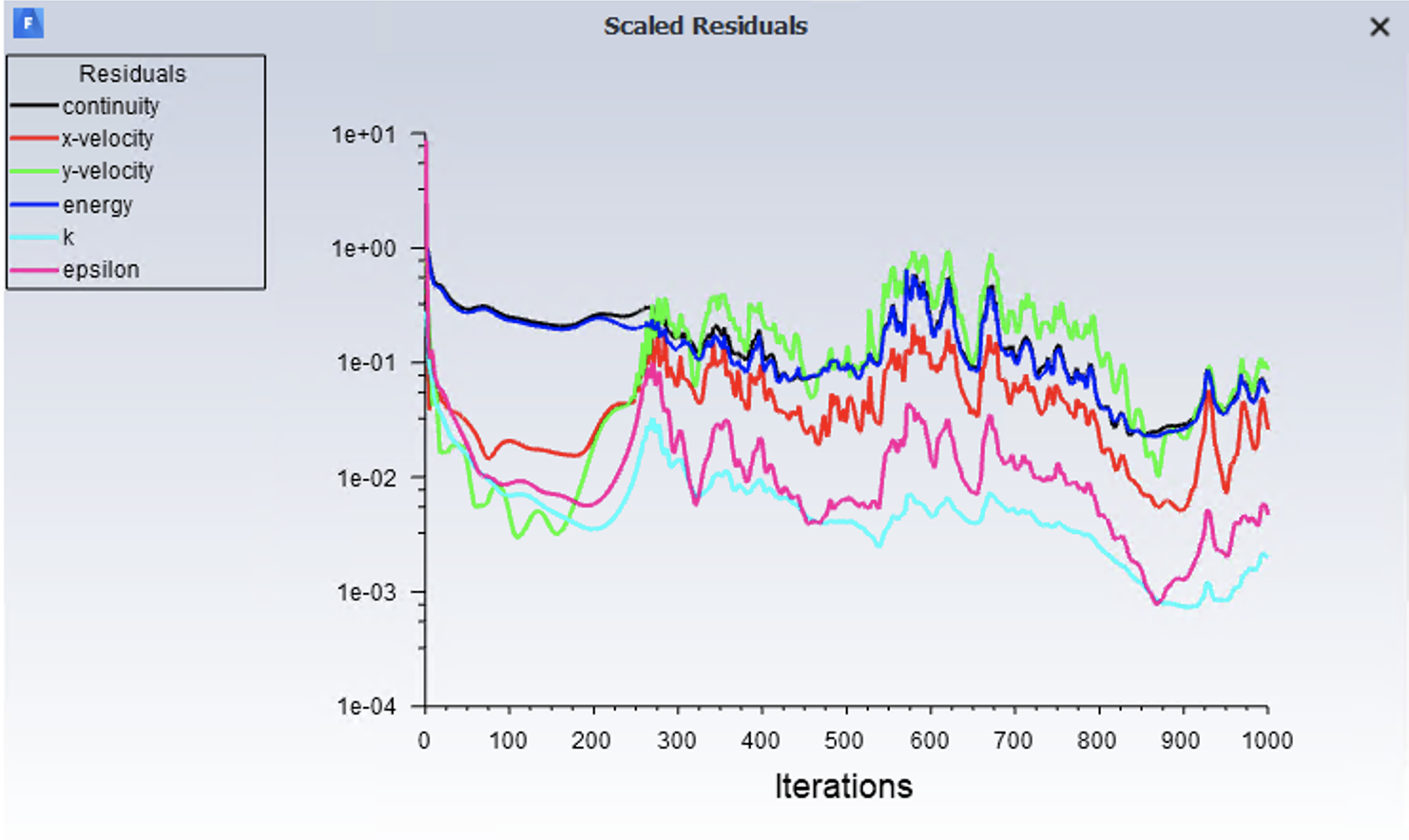
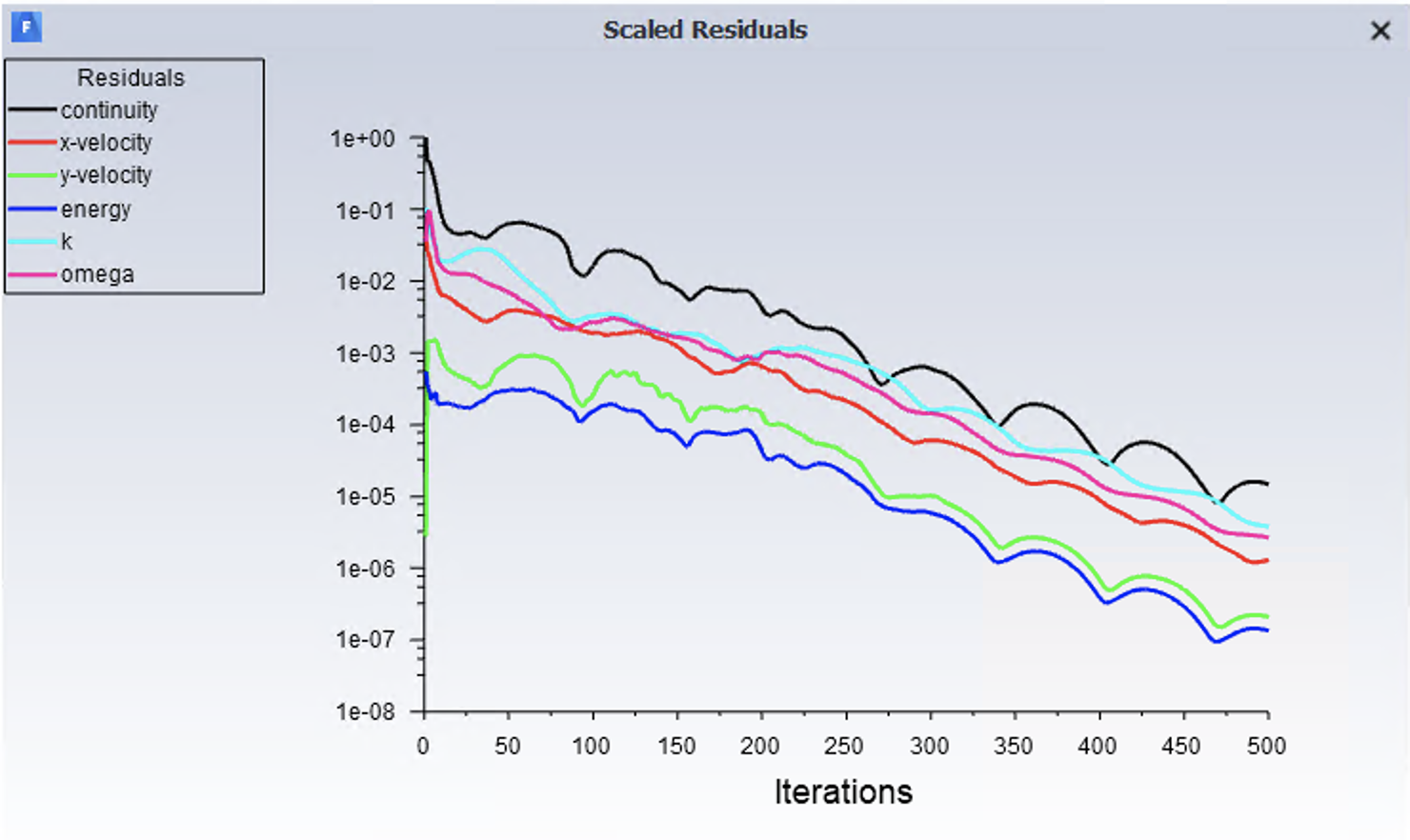
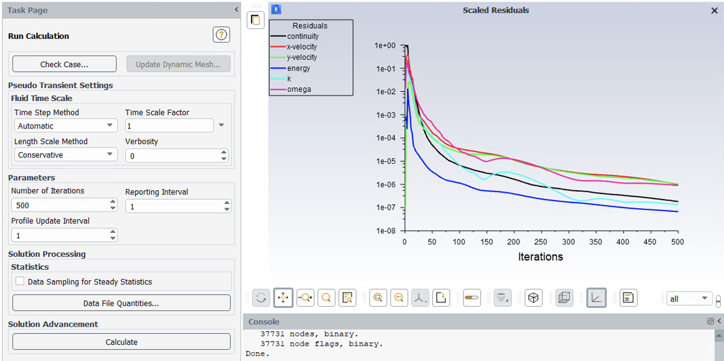
Subscriberplease look at the attached files to see residuals when outlet pressure is 3000 pa and 50000 pa. please let me know how i can send you the code that you can run by yourself. Thank you
August 12, 2021 at 9:46 amAugust 12, 2021 at 1:12 pmSV
SubscriberPlease let me know what do you want me to do and how you want to help
August 12, 2021 at 2:16 pmAugust 12, 2021 at 2:19 pmSV
Subscriberplease look at the pictures to see residuals when outlet pressure is 3000 pa and 50000 pa. you can see the code converge when the outlet pressure is 3000 pa and diverge when the outlet pressure is 50000pa
August 12, 2021 at 3:30 pmRob
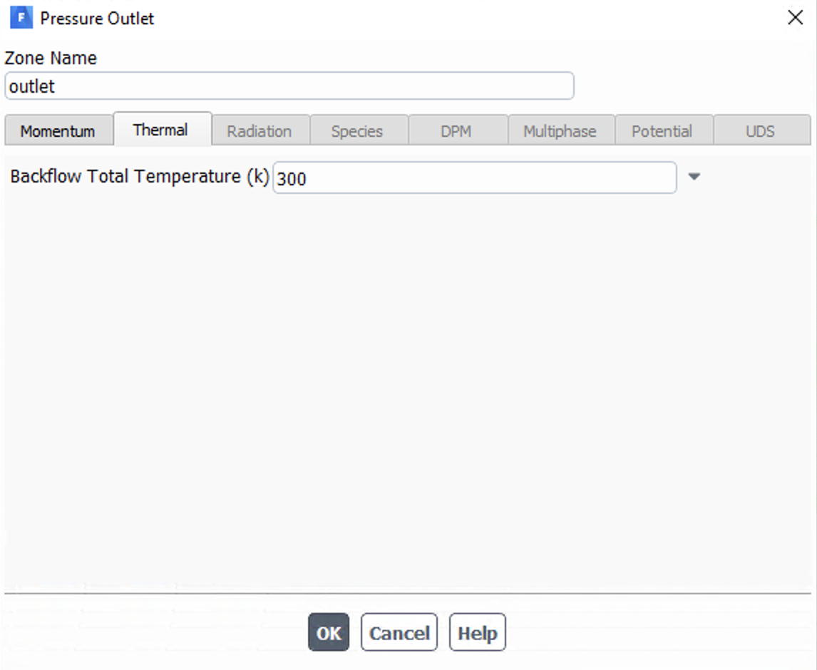
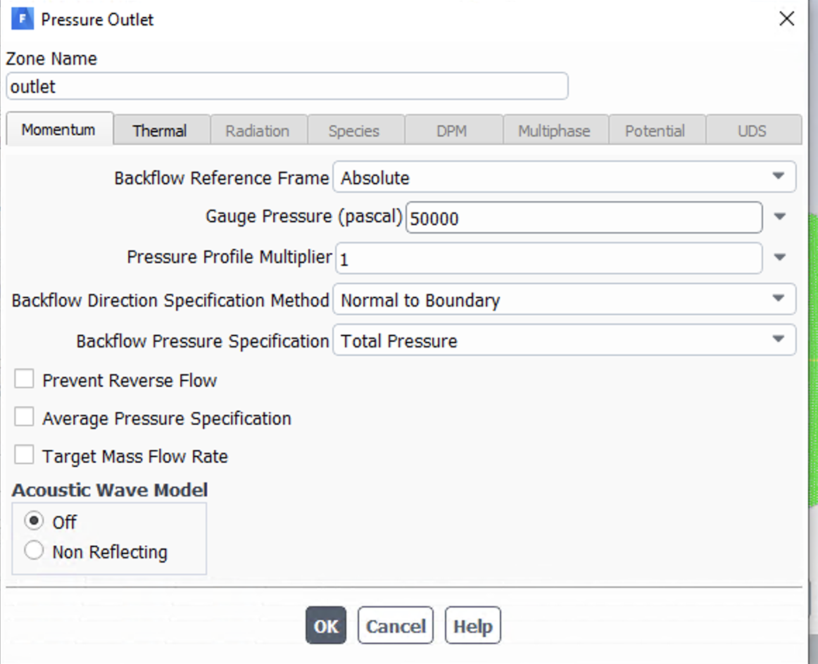
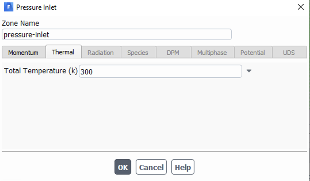
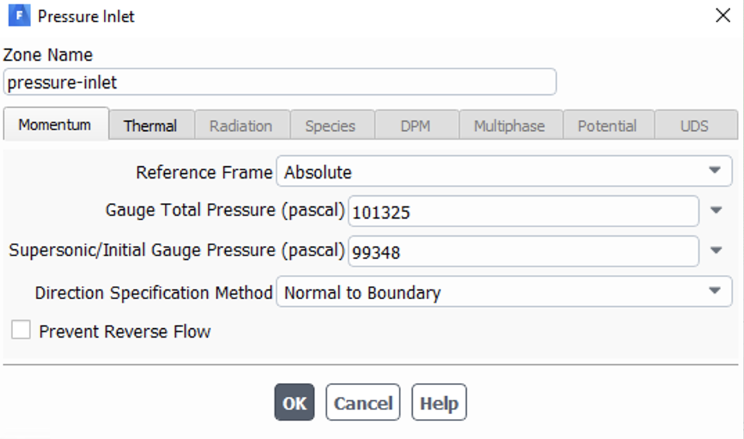
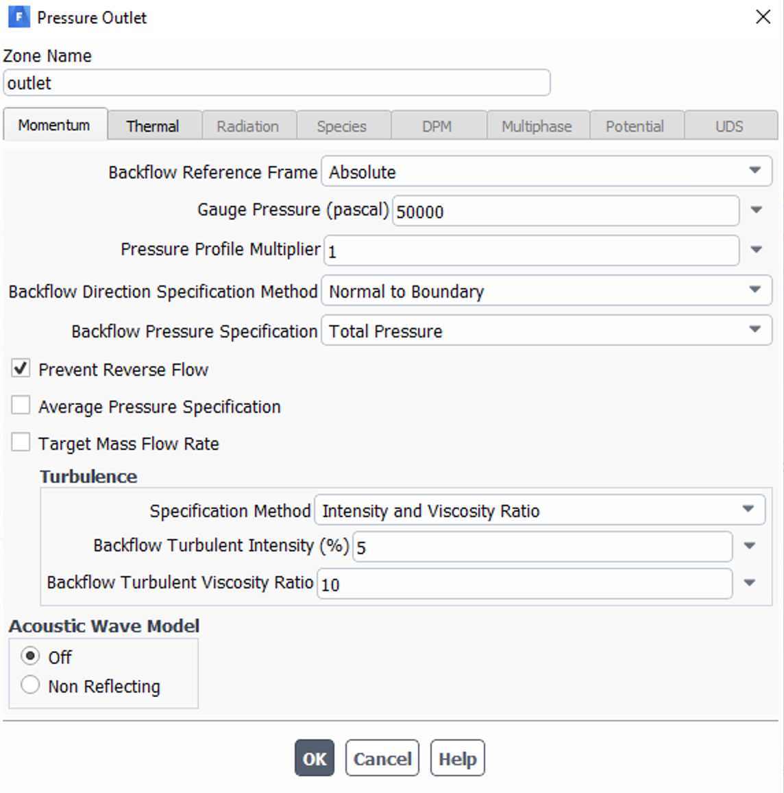
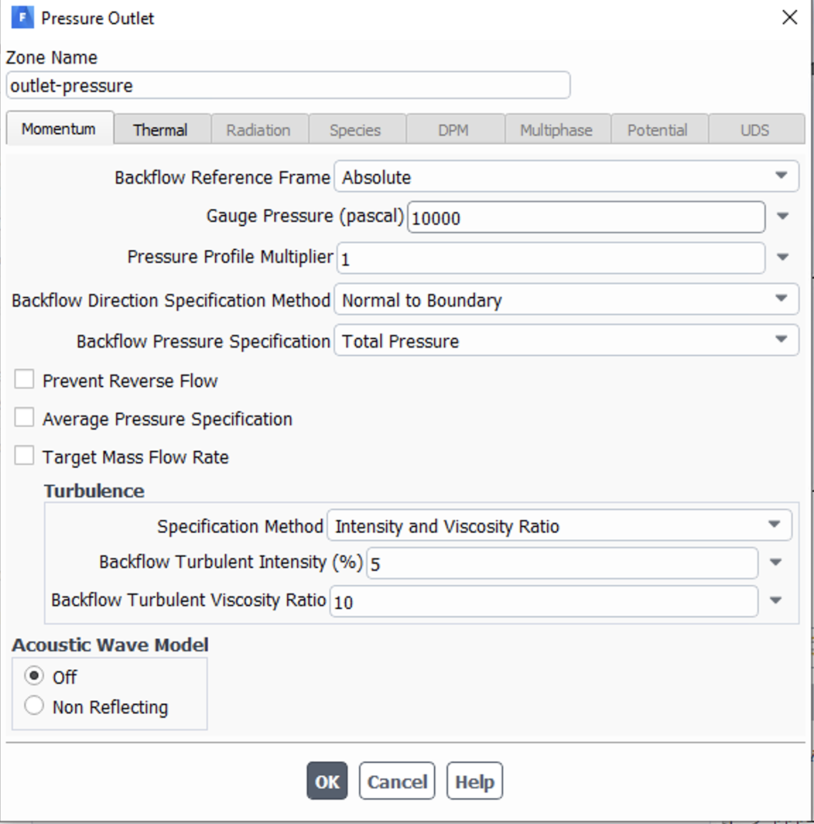
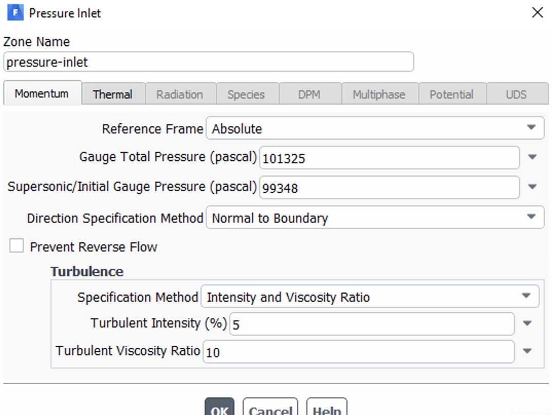
Forum ModeratorWhat's the inlet boundary condition?
August 12, 2021 at 4:59 pmAugust 13, 2021 at 10:07 amRob
Forum ModeratorWhat is the flow field doing just before the model fails?
August 13, 2021 at 1:10 pmSV
SubscriberHello Rob
I do not know what you mean? this model can predict flow if flow is supersonic at outlet. When outlet pressure is 3000 pa, we have supersonic flow at outlet and model works very well. As you increase the outlet pressure the shock wave starts moving toward throat. This model can see the shock wave close to outlet as well but it cannot see further back toward throat.
Thank you
August 13, 2021 at 1:23 pmRob
Forum ModeratorIf you plot & share what's going on in the model we may be able to help. The boundary conditions don't show anything other than it's likely the flow is going in the right direction, so more info needed.
August 13, 2021 at 1:41 pmAugust 13, 2021 at 2:12 pmRob
Forum ModeratorAnd the flow field? What's the Reynolds Number?
August 13, 2021 at 2:17 pmSV
SubscriberWhat you mean by flow field? Re changes because density changes, we are in turbulent flow . Can you please let me know how to plot Re as a function of x
August 13, 2021 at 2:18 pmRob
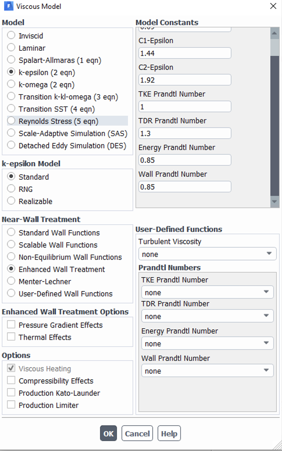
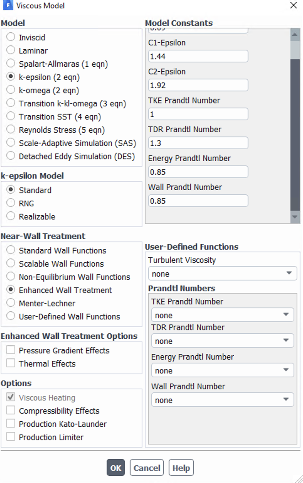
Forum ModeratorWe don't plot Re, you need to calculate it before you start. Which turbulence model are you using?
August 13, 2021 at 2:23 pmAugust 13, 2021 at 2:24 pmSV
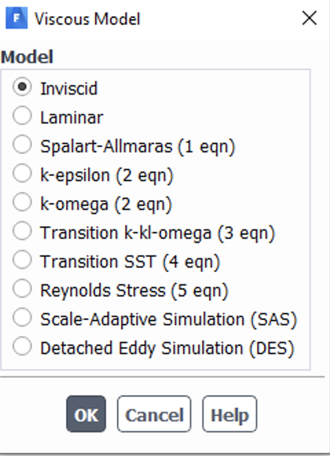
Subscriberi use inviscid model
August 15, 2021 at 12:17 amSV
Subscribercan Ansys predict the location of shock wave at all?
August 16, 2021 at 12:46 pmRob
Forum ModeratorYes it can. Why inviscid if you're modelling shocks in a confined system?
August 16, 2021 at 1:02 pmSV
Subscriberi tried k-epsilon method and we have same issue. iviscid is slightly better, because we do not care what's happening next to the wall. let me know if you want me to send you results for k-epsilon method.
August 16, 2021 at 1:24 pmAugust 16, 2021 at 1:28 pmRob
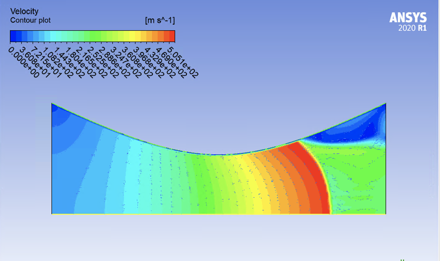
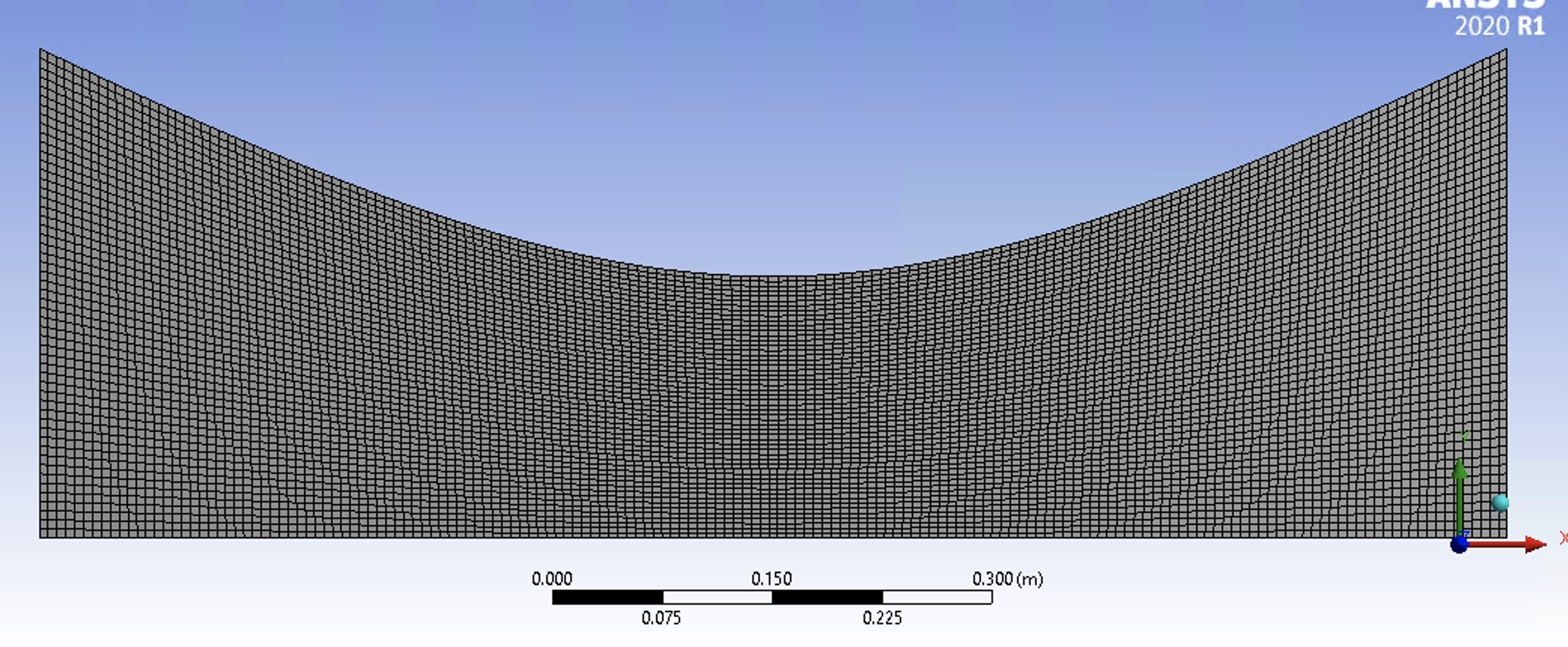
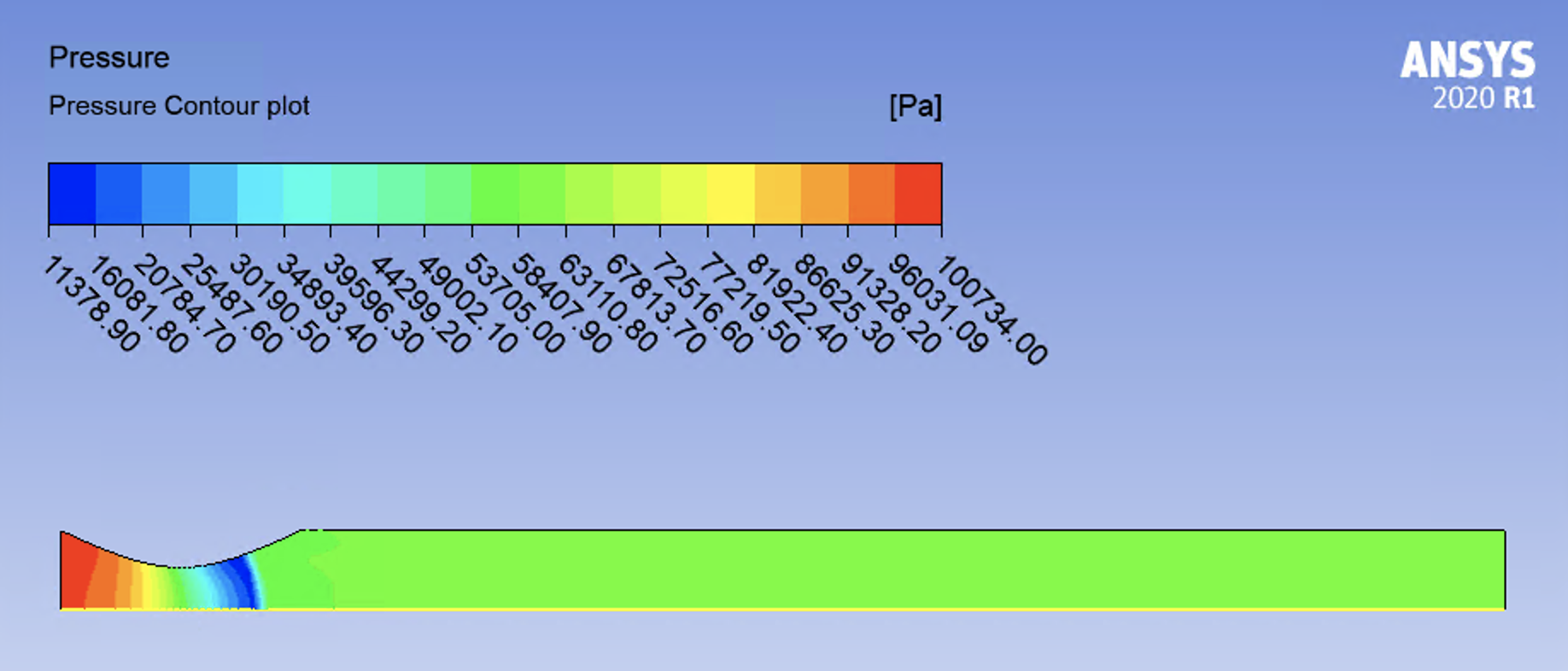
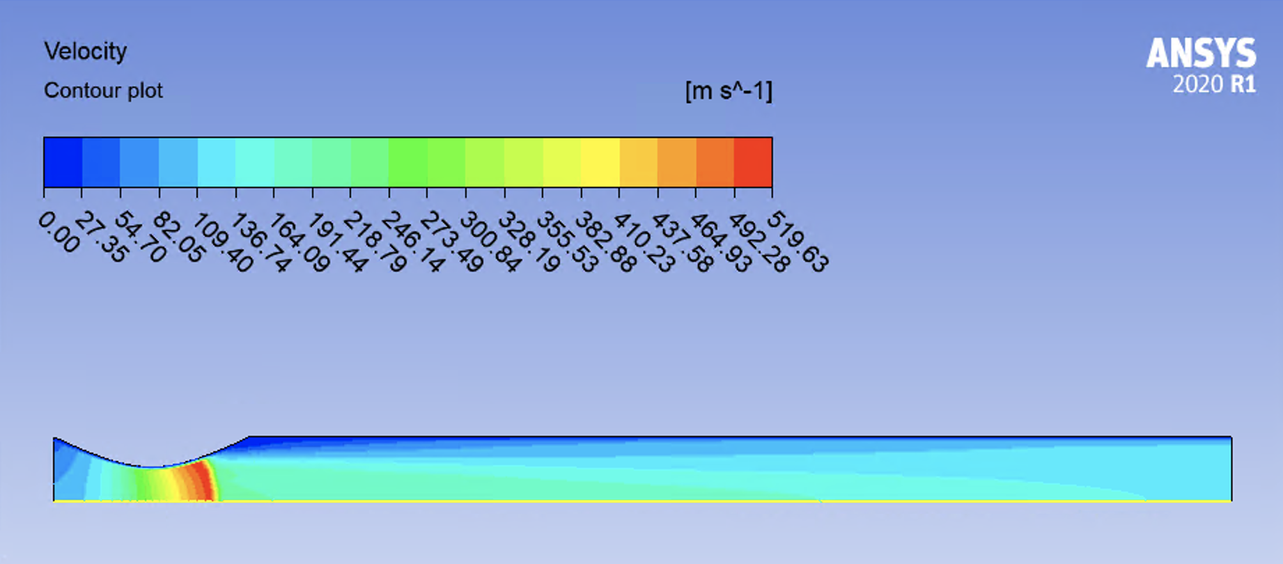
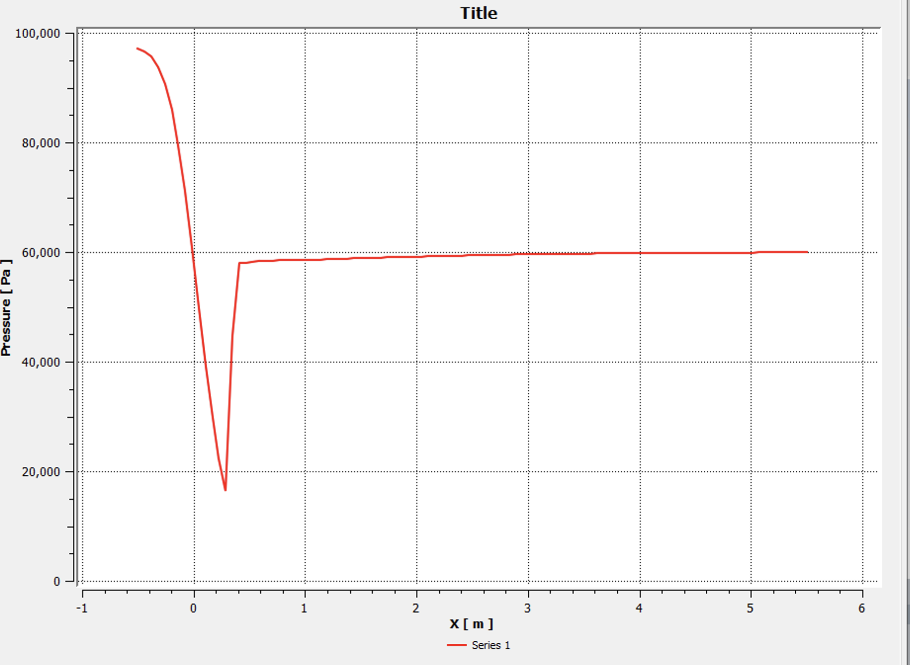
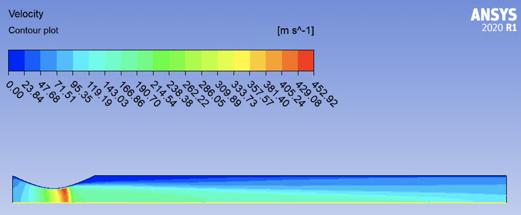
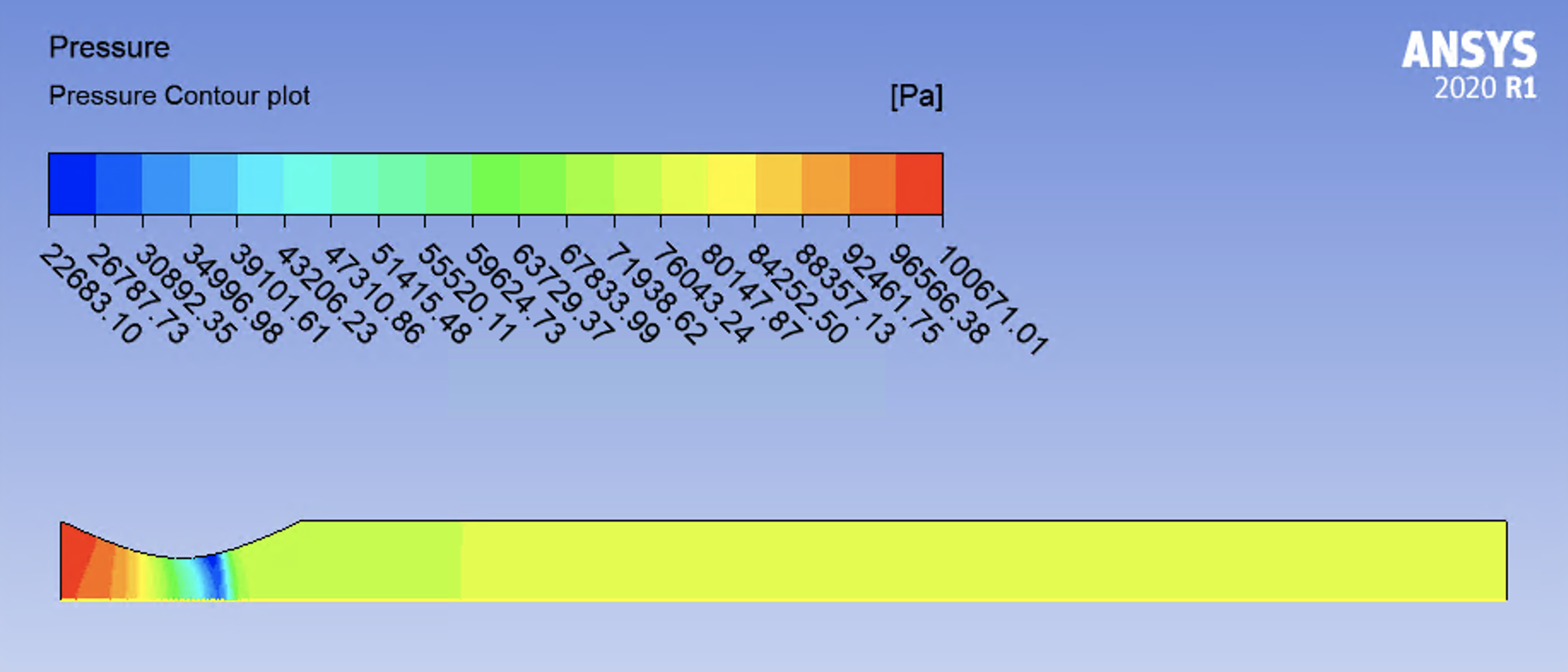
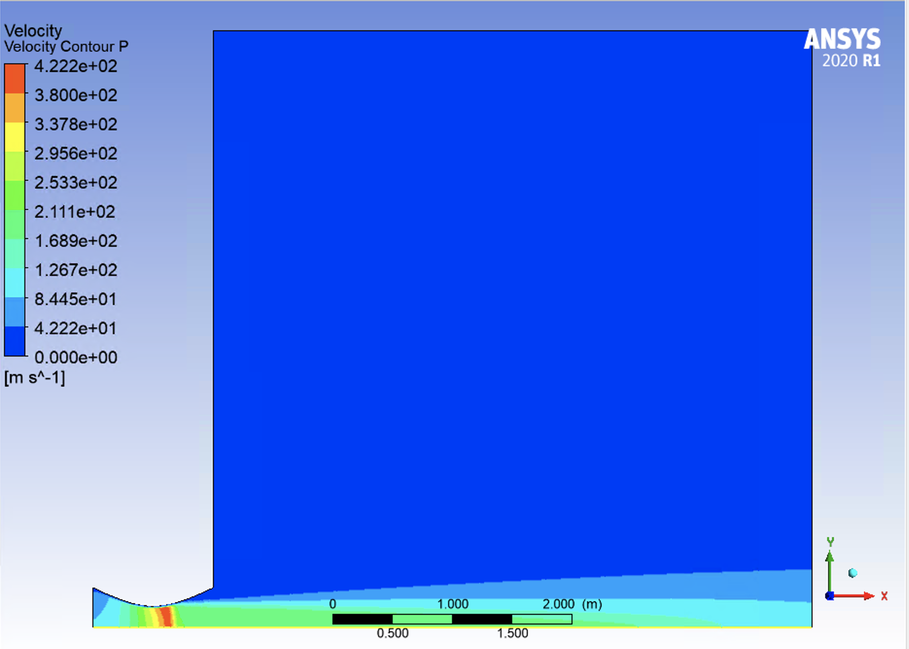
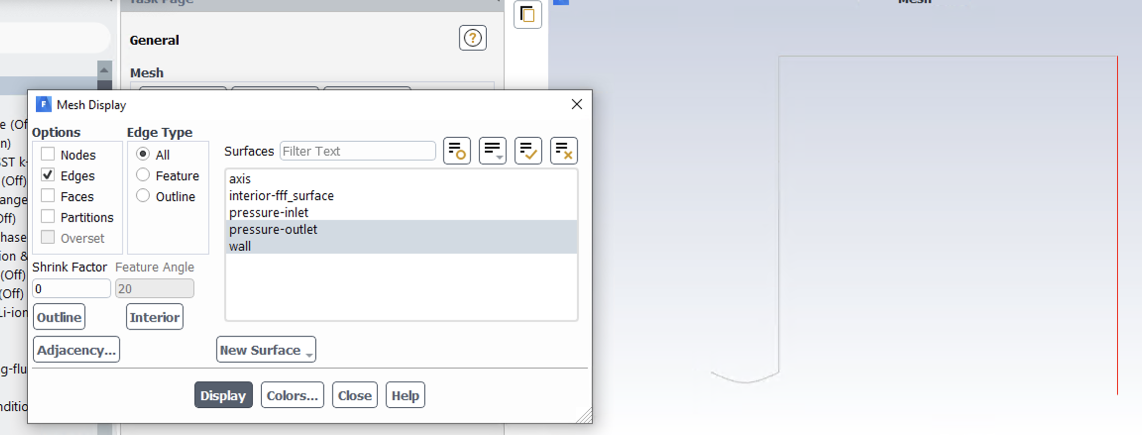
Forum ModeratorPlease can you post some contour & vector plots? Ie enough information to actually figure out what's going on? An image of the mesh will help too.
August 16, 2021 at 2:01 pmSV
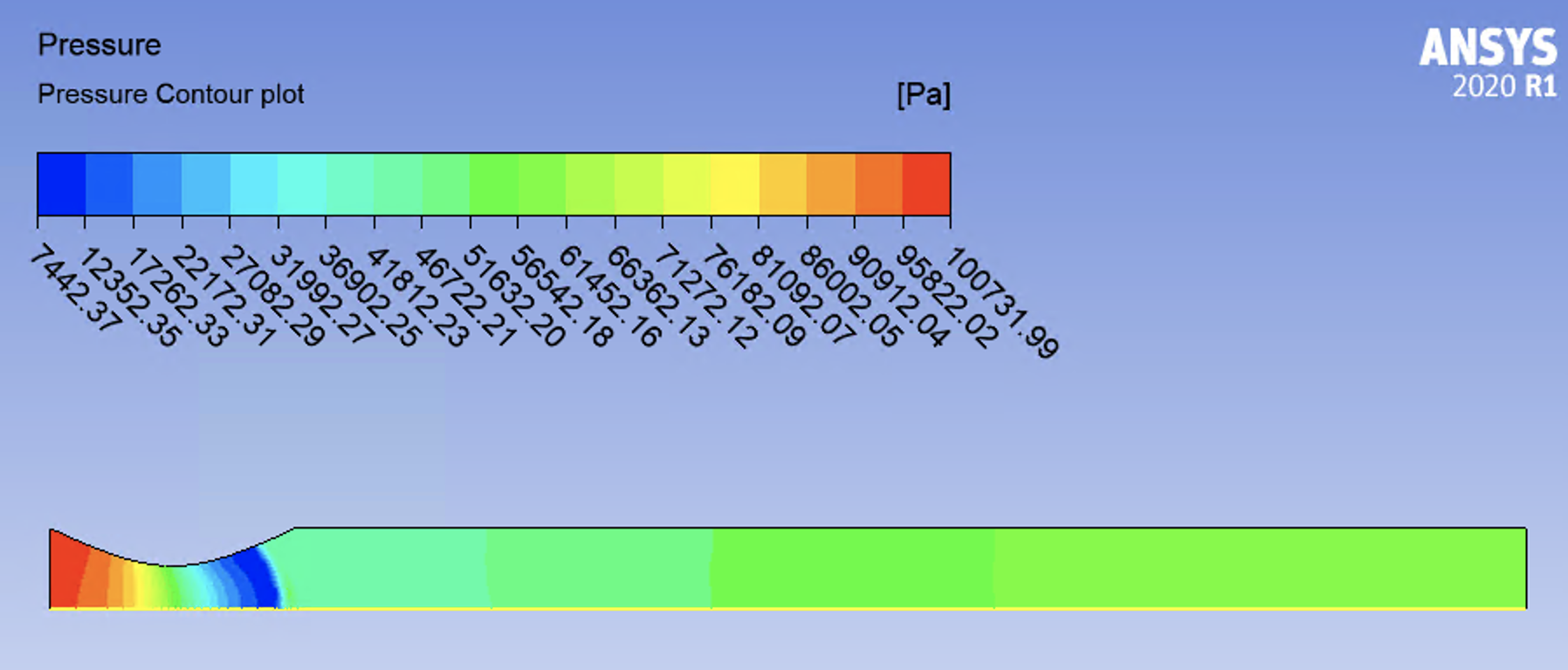
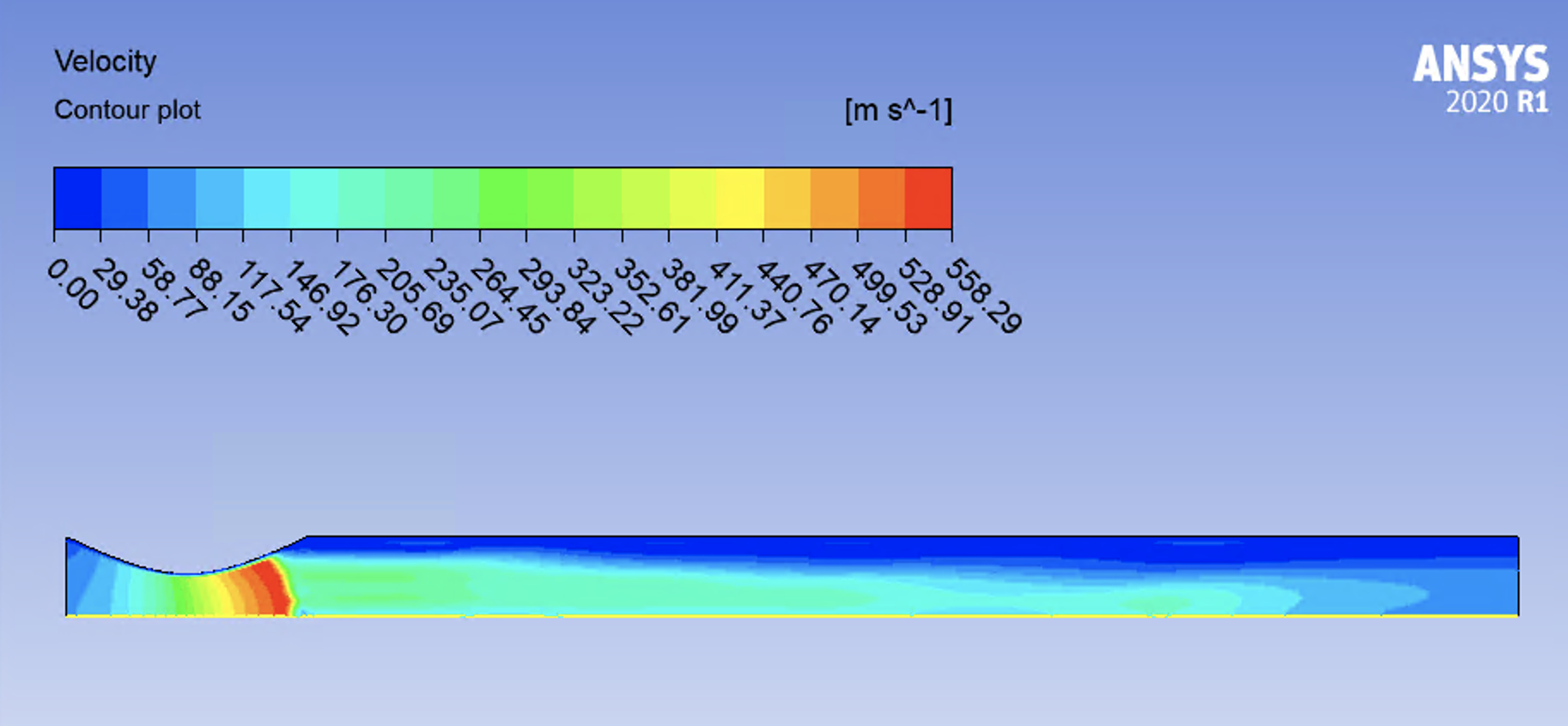
SubscriberPlease look at following figures
August 16, 2021 at 2:02 pmAugust 16, 2021 at 3:35 pmRob
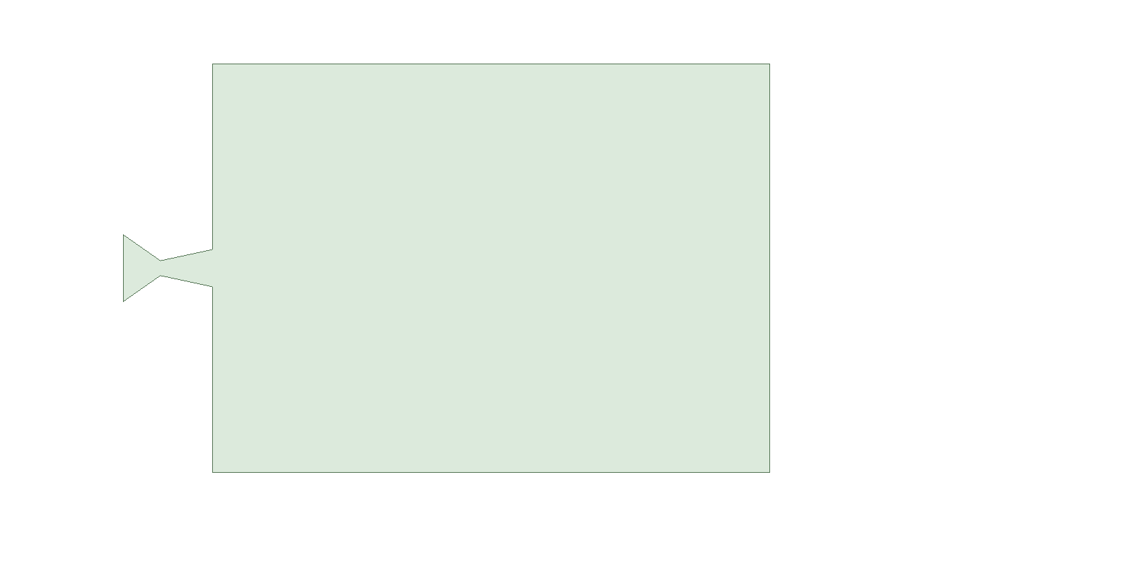
Forum ModeratorExtend the domain by at least 5-6 diameters in each direction. Your shocks are far too close to the boundary and using "no reverse" flow is causing you problems. Post process in Fluent too, you may need some of the data that's not moved to CFD Post by default.
If you look under courses at the top of the page you'll see some that are very relevant to this problem.
August 16, 2021 at 4:17 pmSV
SubscriberHello
I removed the "no reverse" flow. Still I have problem and data doesn't move to to CFD Post by default. Can you please send me the link you mentioned. I would rather to keep the geometry as it is.
August 16, 2021 at 4:39 pmRob
Forum ModeratorScroll up, just to the right of "Ansys Learning Forum" look at Courses.
Depending on where the shock is, you're forcing the solution with the boundaries being too close: it's not a preference to retain the current domain but a need to extend it. Or revise the boundary condition to be exactly what the solver would calculate at that location.
August 16, 2021 at 4:42 pmSV
SubscriberPlease let me know if you have suggestions for boundary conditions. I am keep changing the boundary conditions to see if i can fix the issue. Changing boundary conditions is a better idea
August 17, 2021 at 2:36 amSV
SubscriberHello
I kept the ratio almost same and reduced the inlet and outlet pressures. Still I have same issues.
August 17, 2021 at 6:56 amaitor.amatriain
SubscriberAs suggests, you should increase the size of the domain. It is important to include the whole nozzle, plus a zone such that the pressure at the outlet is of the order of ambient pressure. It is also a good practice to include a boundary layer on the walls of the nozzle, in order to predict accurately the separation point that leads to the generation of shock waves in the diverging part of the nozzle (as you may know, this happens in some interval of the ratio between stagnation pressure and ambient pressure).
August 17, 2021 at 7:58 pmSV
SubscriberHello
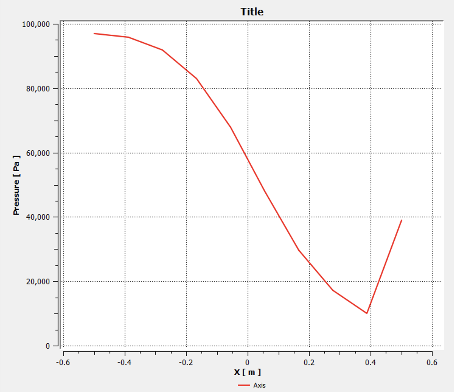
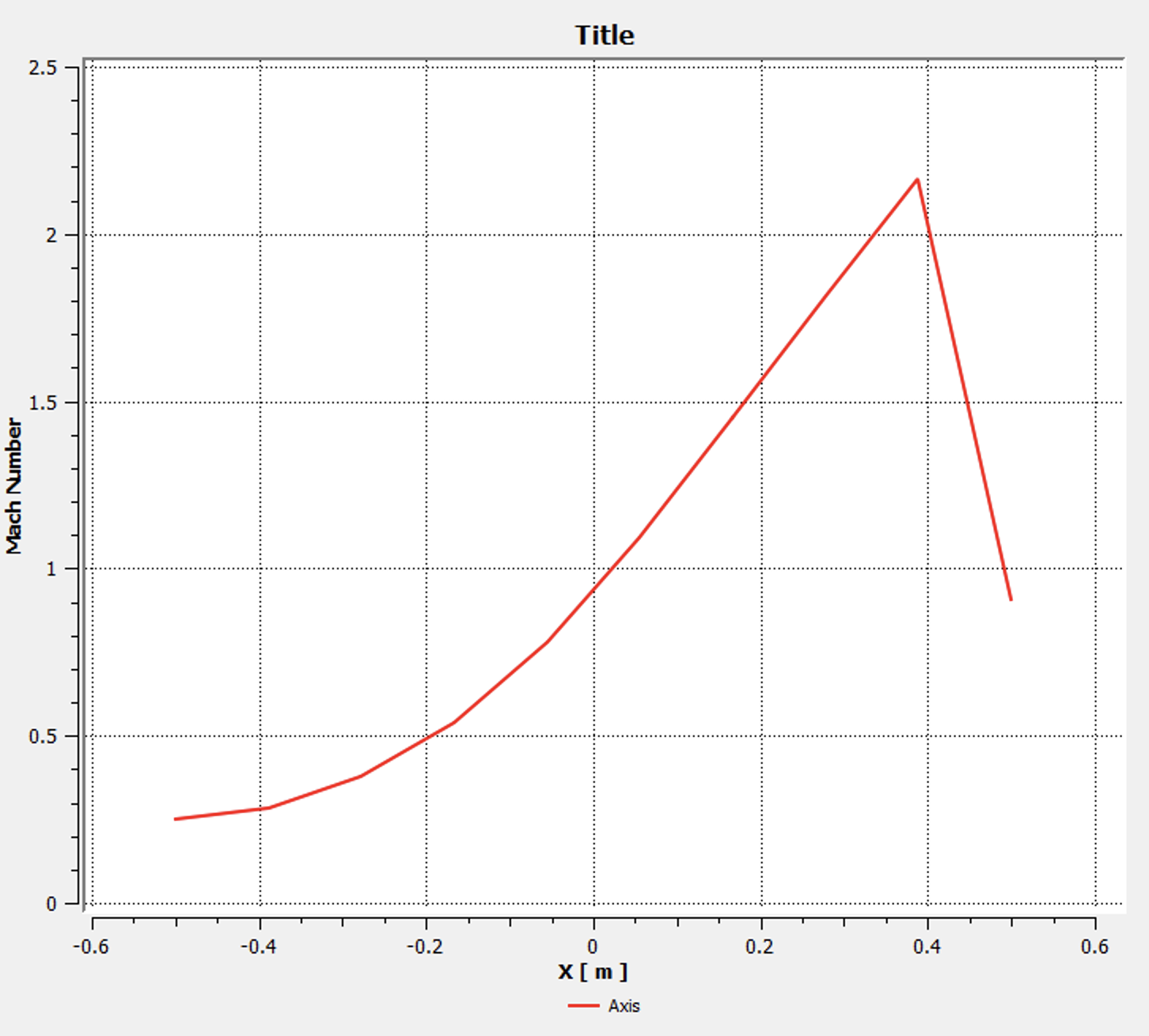
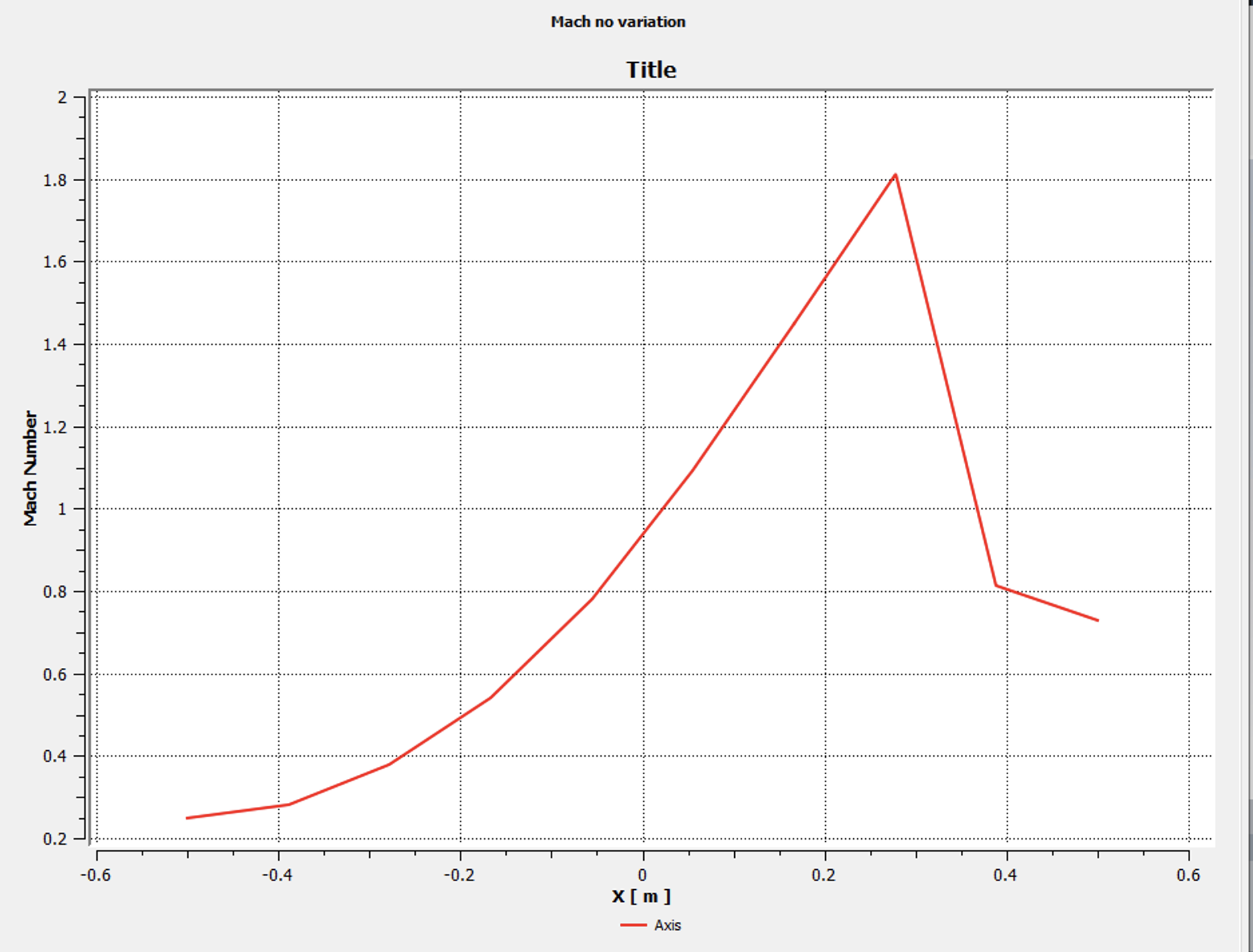
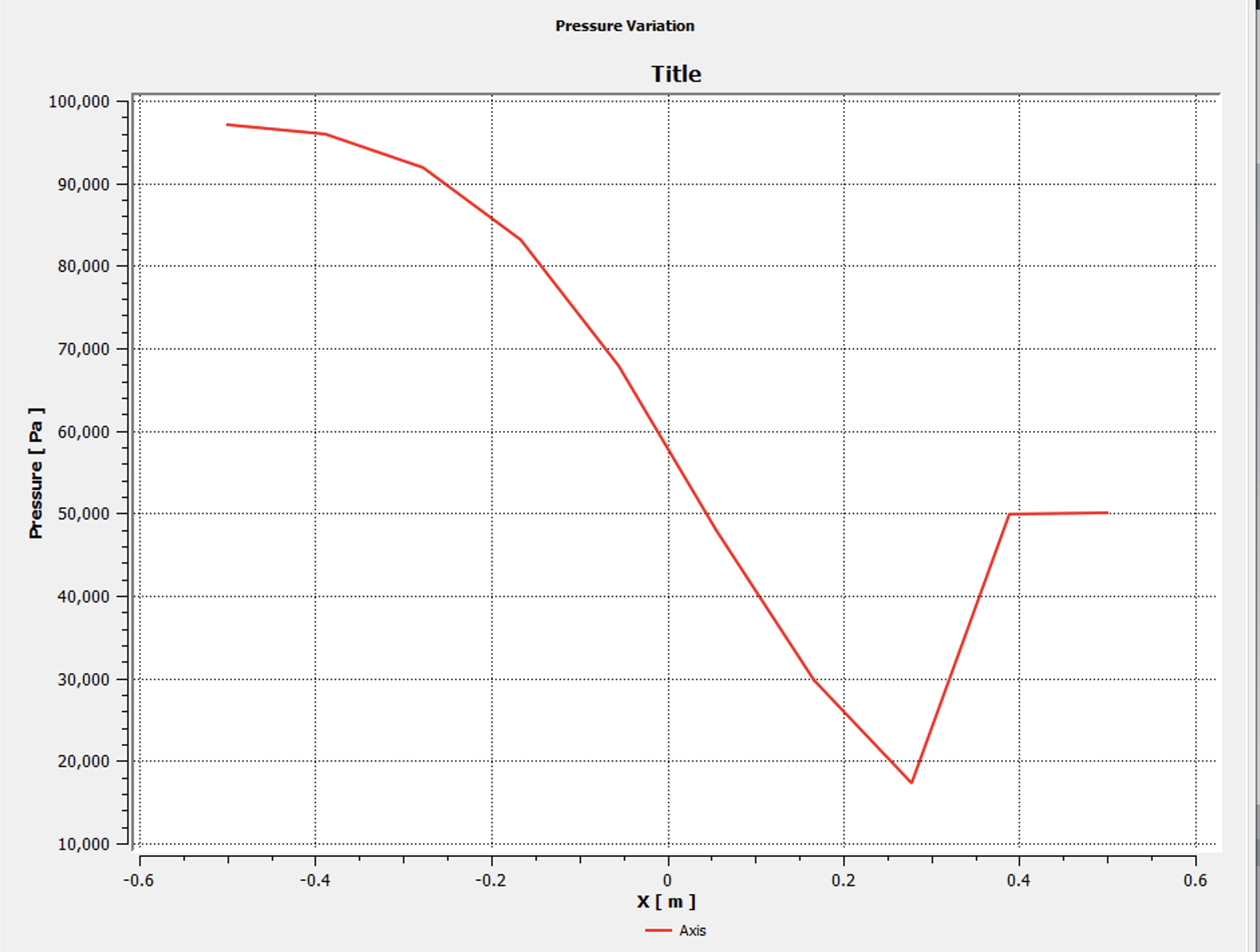
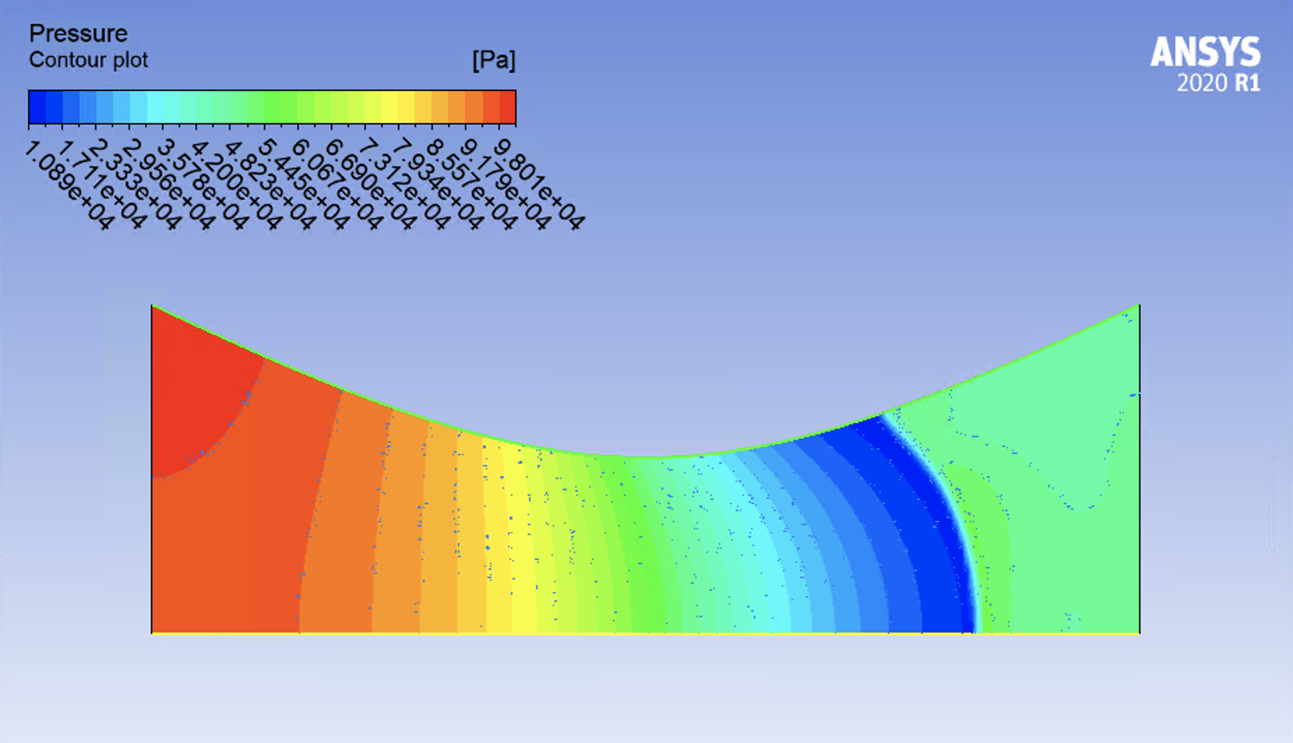
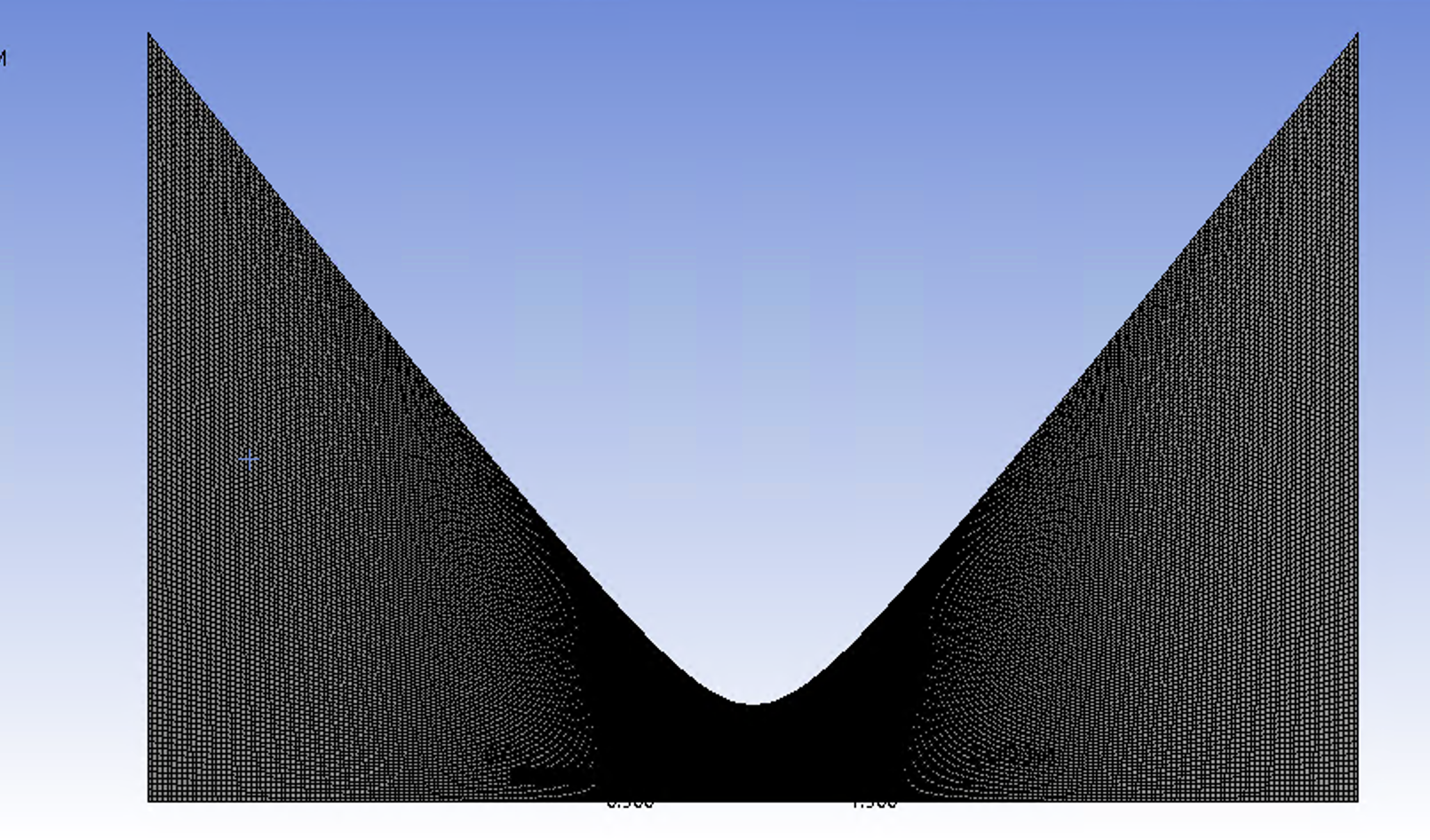
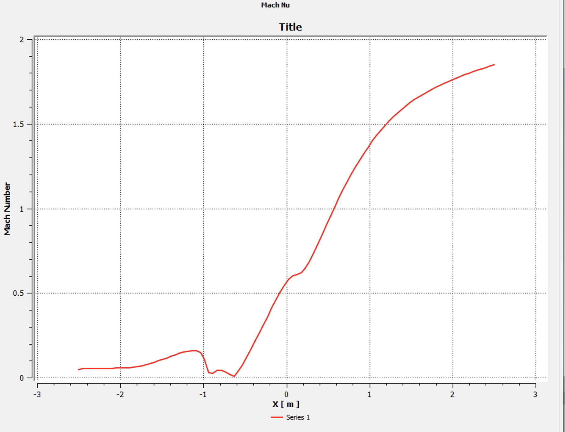
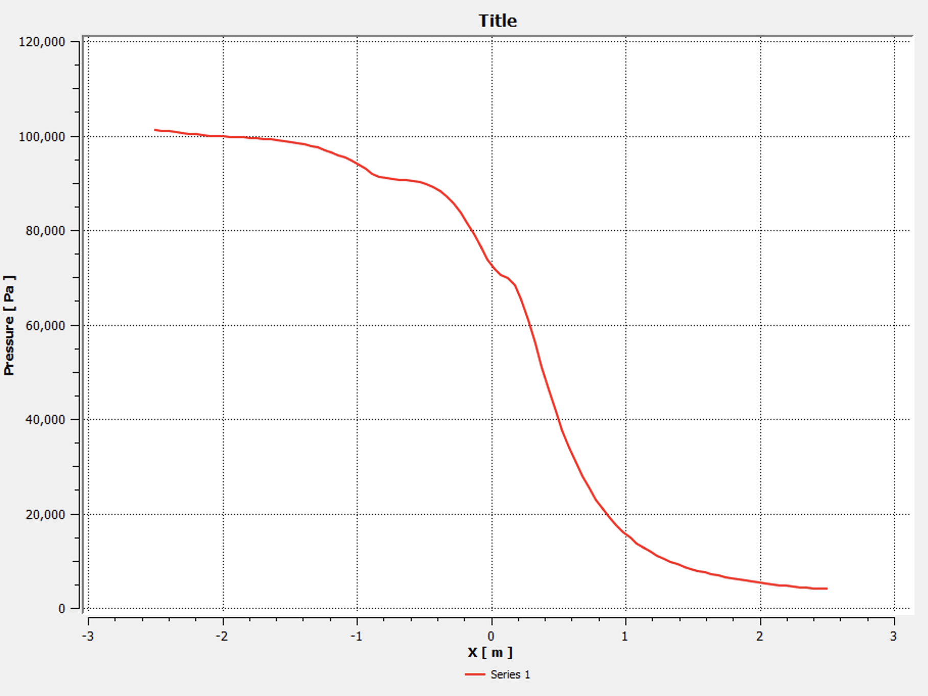
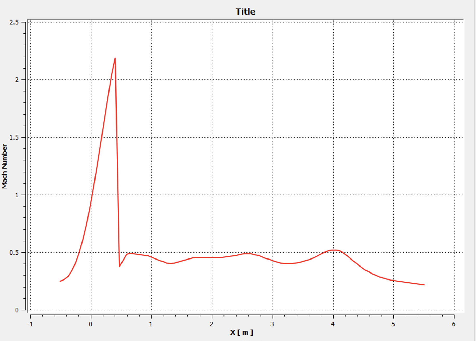
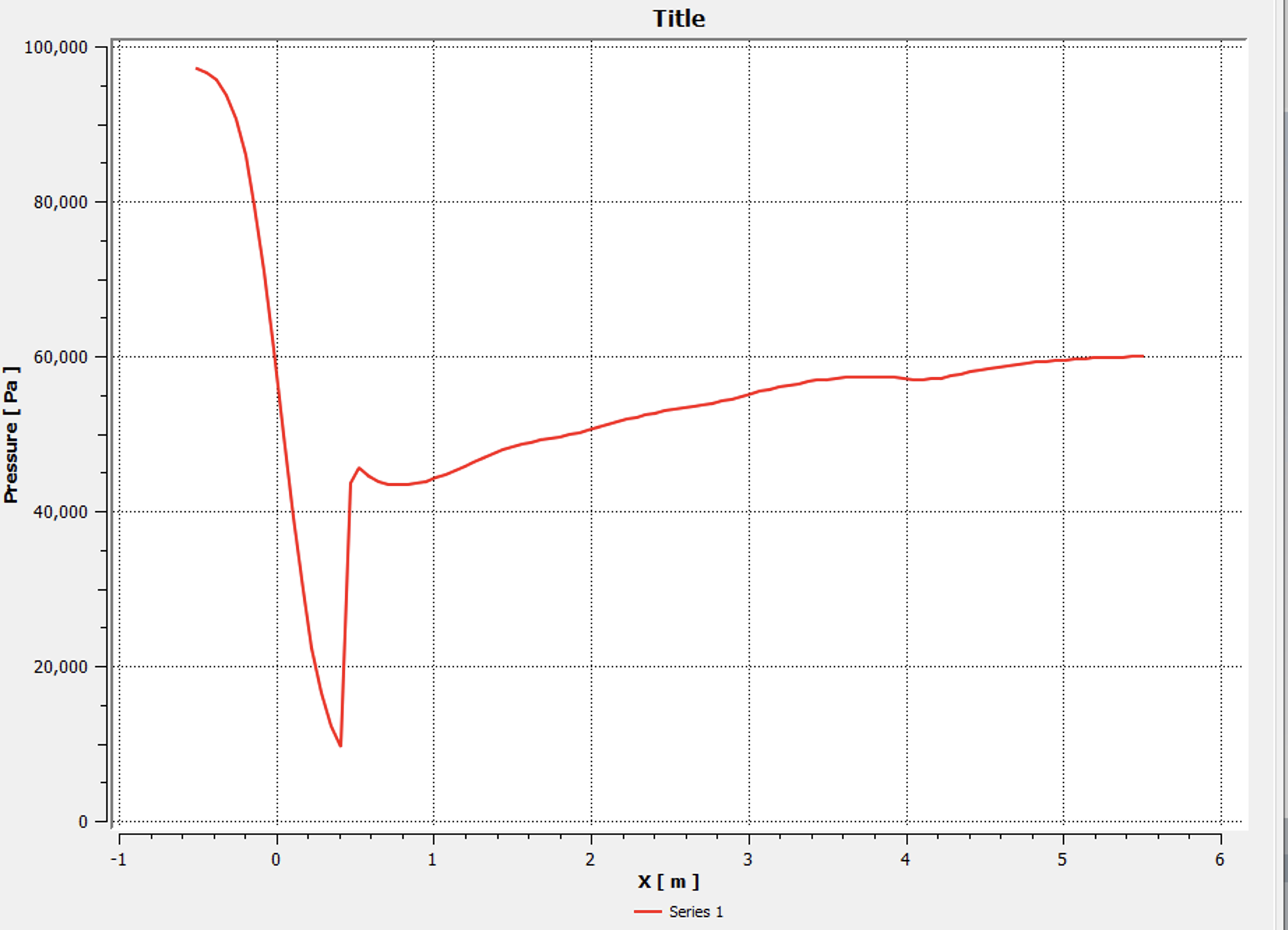
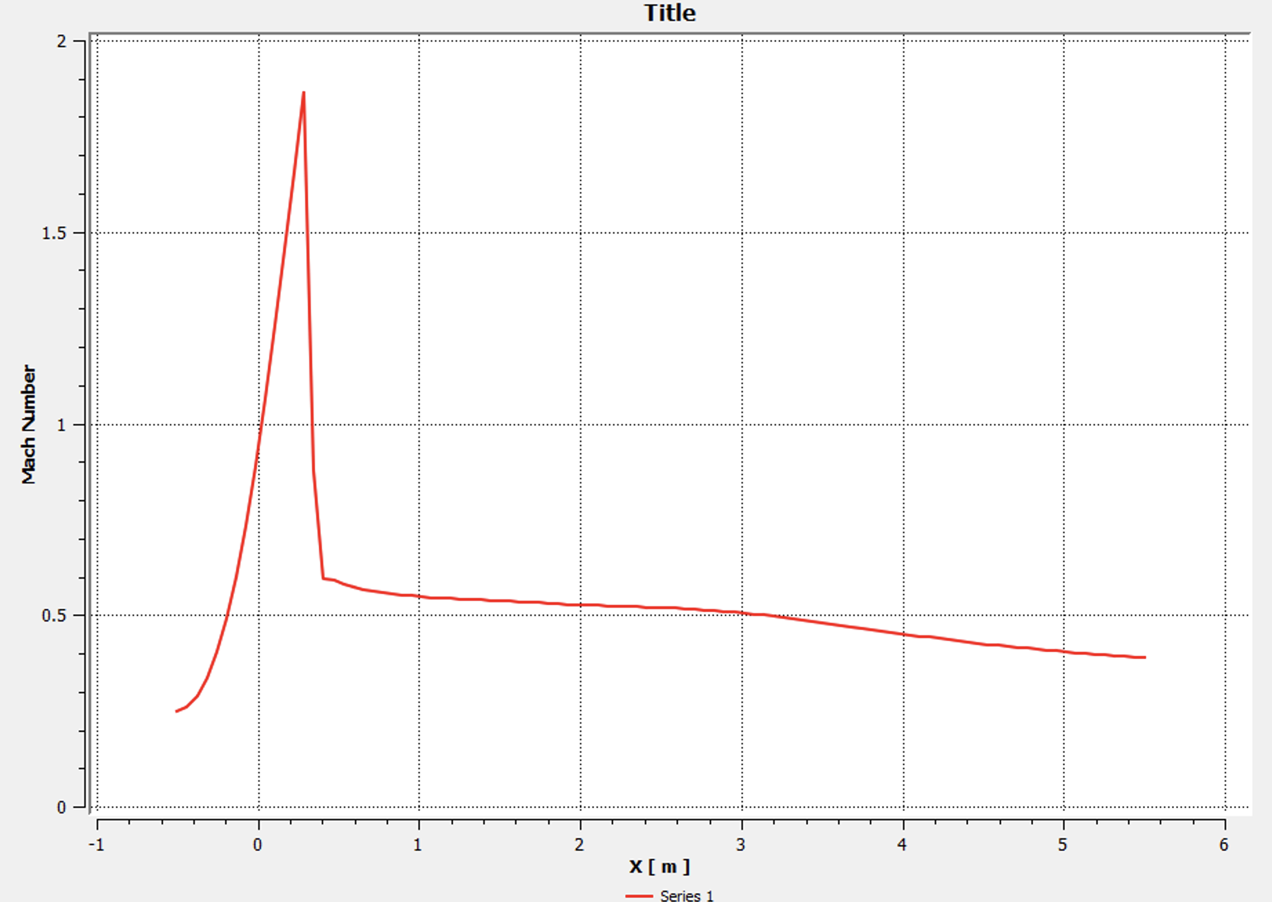
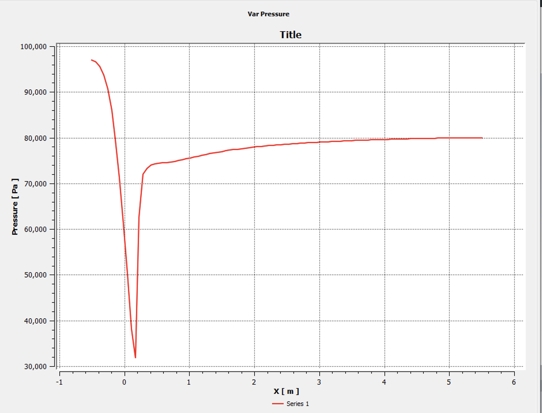
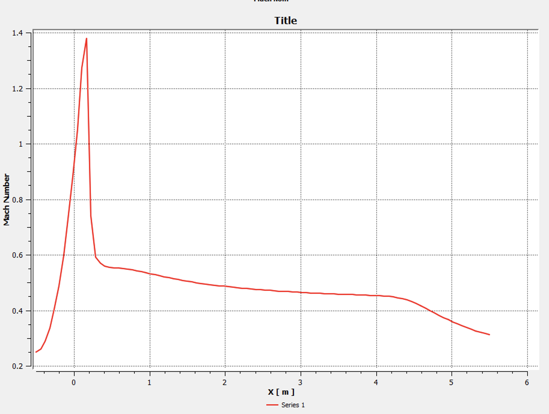
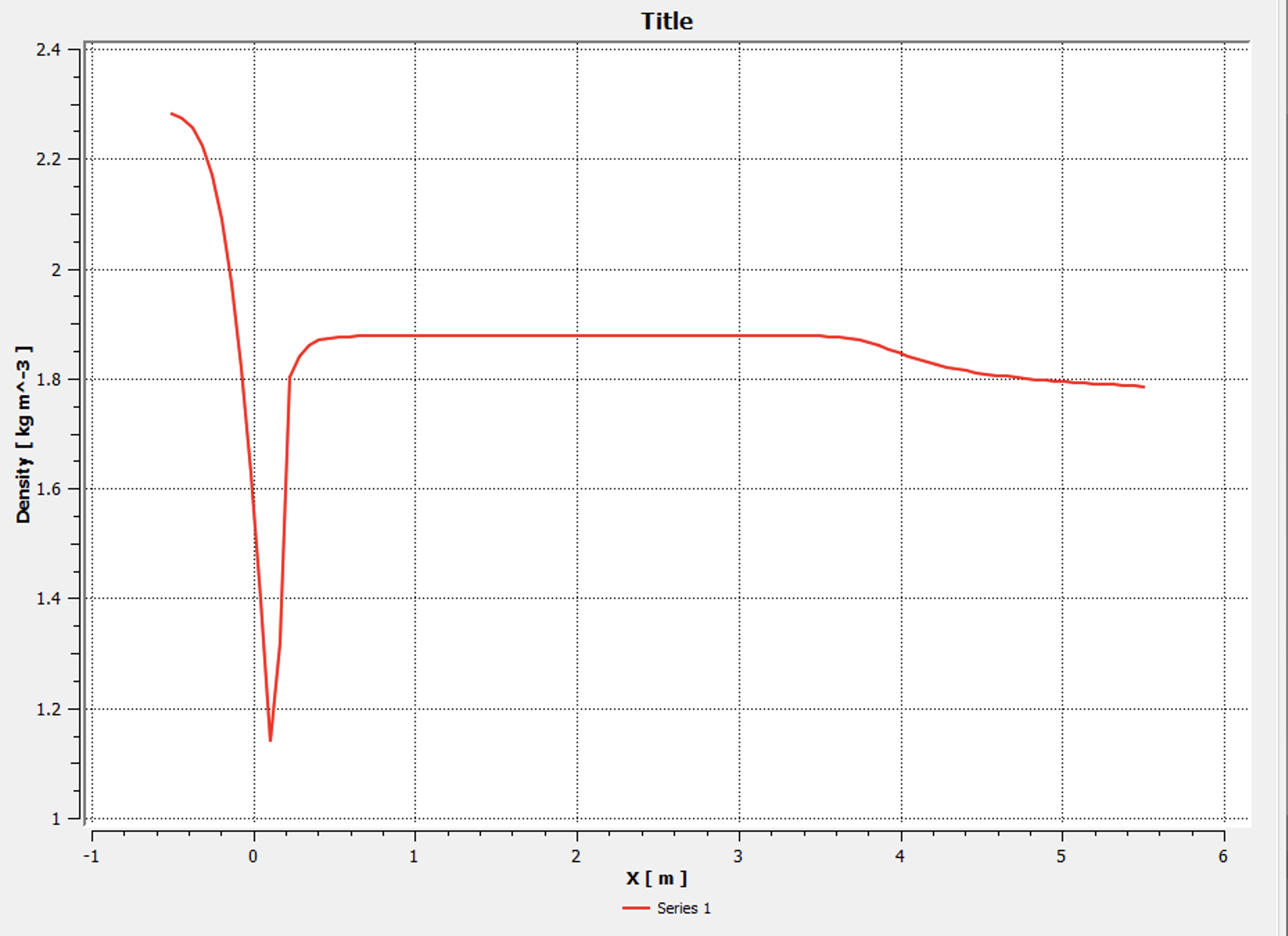
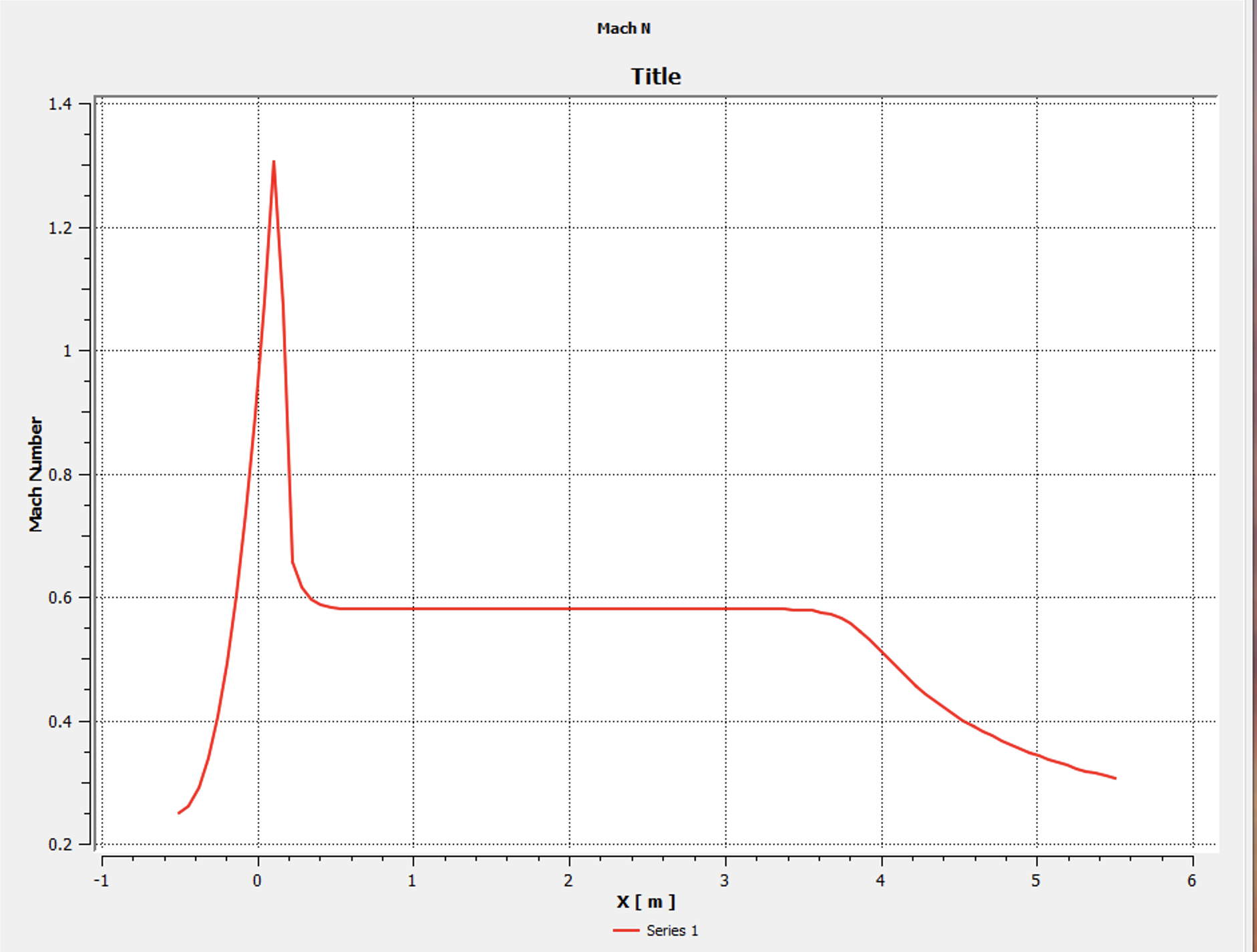
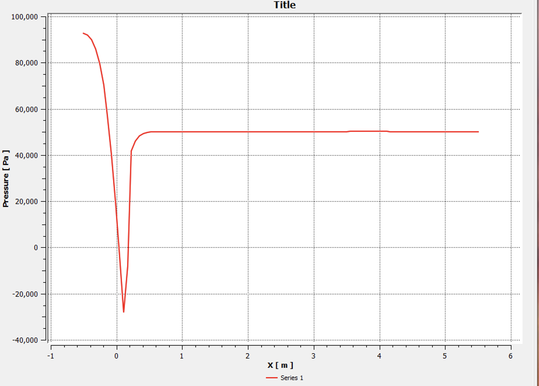
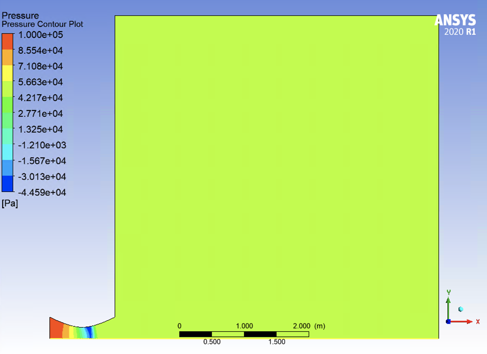
i increased the domain five times as it was suggested. I cannot see the shock wave correctly now. I will send you some figures, let's start to check step by step and i will follow your suggestions
August 17, 2021 at 8:10 pmAugust 17, 2021 at 9:11 pmSV
Subscriberplease look at variation of mach number carefully.
August 18, 2021 at 6:48 amaitor.amatriain
SubscriberYou have modified the geometry of the nozzle, and that is supposed to be fixed. My suggestion was to extend the geometry outside nozzle outlet.
Your problem will not be in hypersonic regime, so I would choose the pressure-based solver with the default settings (k-omega SST, second order discretization)
August 19, 2021 at 12:05 amAugust 19, 2021 at 12:06 amAugust 19, 2021 at 12:28 amAugust 19, 2021 at 6:57 amAugust 19, 2021 at 10:30 amRob
Forum ModeratorThanksAugust 19, 2021 at 11:09 amaitor.amatriain
SubscriberYou are welcome!
EDIT: I did not see the question "Can you please explain when we can use density based and when pressure based".
Fluent's User Guide give some information about this topic:
32.1. Overview of Using the Solver (ansys.com)
August 19, 2021 at 3:29 pmAugust 20, 2021 at 6:45 amaitor.amatriain
SubscriberGood!
August 20, 2021 at 12:07 pmSV
SubscriberHello
I am looking for couple of clips to explain 3D, single flow (like t-fitting, elbow, etc) simple geometries for educational purposes. i would rather to have clips to start explaining from making geometry to meshing, solving and post processing. Please let me know if you know if you know where i can find.
Thank you
August 20, 2021 at 12:37 pmRob
Forum ModeratorOther than the AIC and YouTube content plus Help there isn't anything as we mentioned here /forum/discussion/30621/effective-video-clips-to-learn-about-new-spaceclaim-geometry#latest For simple examples you may be better with the Cornell materials?
August 21, 2021 at 5:38 pmSV
SubscriberHello
I have checked with Cornell University, They are 2D. Thank you
August 21, 2021 at 5:40 pmSV
SubscriberI have a T-pipe with two inlets and one outlet. It diverges. Would you like to help with that?
Thank you
August 23, 2021 at 8:36 amaitor.amatriain
SubscriberPlease create a new post and give details of the simulation (Models, solver settings, screenshots of the mesh and contours...)
August 23, 2021 at 11:30 pmSV
Subscriber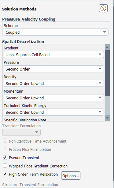 Hello
Hello
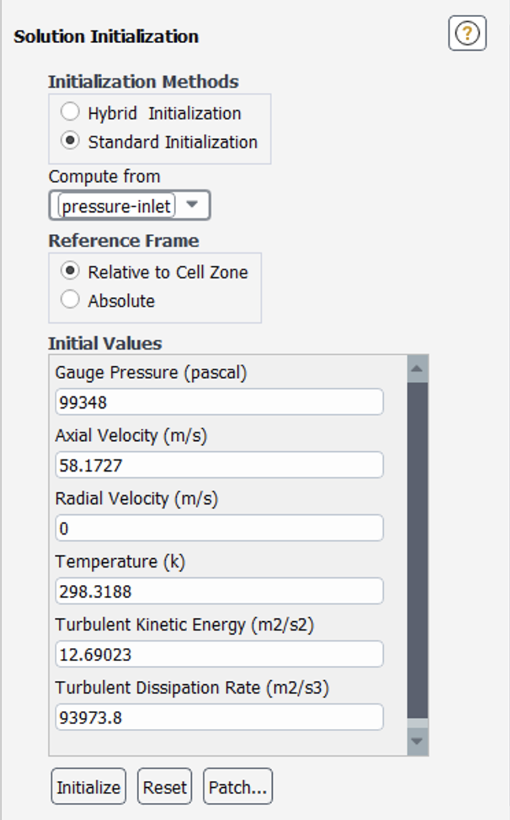
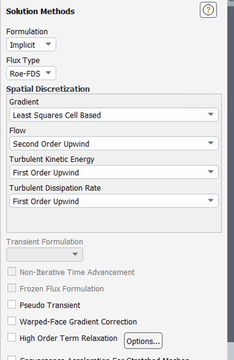
Thank you for helping on converging-diverging nozzle. Please look at figure to see my solution methods for converging-diverging nozzle. May i ask you where i can find information about Scheme (coupled), Gradient (least squares cell based), Pressure (second order) Density (Second order Upwind) etc.
August 24, 2021 at 6:45 amaitor.amatriain
SubscriberPractical aspects are covered in the User's Guide Chapter 32: Using the Solver (ansys.com)
while additional aspects related to the theory are given by the Theory Guide:
Chapter 24: Solver Theory (ansys.com)
Viewing 50 reply threads- The topic ‘converging- diverging nozzle’ is closed to new replies.
Innovation SpaceTrending discussionsTop Contributors-
4683
-
1565
-
1386
-
1242
-
1021
Top Rated Tags© 2025 Copyright ANSYS, Inc. All rights reserved.
Ansys does not support the usage of unauthorized Ansys software. Please visit www.ansys.com to obtain an official distribution.
-


Ansys Assistant

Welcome to Ansys Assistant!
An AI-based virtual assistant for active Ansys Academic Customers. Please login using your university issued email address.
Hey there, you are quite inquisitive! You have hit your hourly question limit. Please retry after '10' minutes. For questions, please reach out to ansyslearn@ansys.com.
RETRY
