
-
-
September 16, 2020 at 10:50 am
Jasmin
SubscriberI'm solving 2D axis-symmetric problem when I apply required differential pressure on inside and outside surface. I get error solver unable to converge nonlinear problem. Due to elements getting distorted at contact region which I found from newton Raphon residual force. I have tried with finer mesh and changing contact parameter. If anyone with some suggestion will be really helpful.
September 16, 2020 at 5:21 pmpeteroznewman
SubscriberIt will be much easier to give a helpful suggestion if you show an image of the geometry.nSeptember 17, 2020 at 12:39 pmSubscriberI want to compress the C shape structure between 2 plates in LS1 and apply temperature and differential pressure in LS2. In order to ramp load I have created 5 steps as there was convergence issue. I'm doing this in Ansys workbench. Also I was trying to set convergence criteria as mesh so that remeshing will be done to get to convergence but I was not able to do that setting.n n
September 18, 2020 at 12:01 pmSubscriberIf the temperature load is symmetric, one suggestion is to use a horizontal plane of symmetry, then you can have just one plane moving toward that plane. n
n
September 18, 2020 at 12:01 pmSubscriberIf the temperature load is symmetric, one suggestion is to use a horizontal plane of symmetry, then you can have just one plane moving toward that plane. n Don't try to use automatic remeshing. Is the C shaped piece a hyperelastic material?n
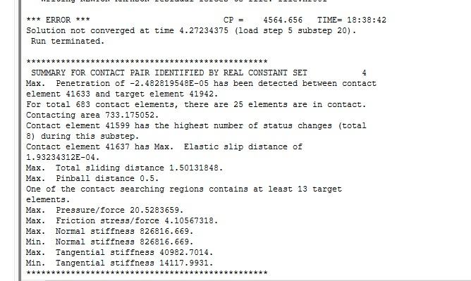
September 19, 2020 at 6:50 pmSubscriberNo C shaped component is metal. I have been doing entire model in static structural in workbench and applied thermal condition by setting reference temperature of component as 'by body' which is uniform. I will try making the horizontal plane of symmetry. In error file it says too much penetration of contact element into target and also some element are getting highly distorted near contact region. Main problem arises when differential pressure load is applied on inside and outside surface of C at that point only convergence issue is coming. If you see force convergence image it's the step5 where full differential pressure load is applied solver is unable to converge.nSeptember 20, 2020 at 12:49 amSubscriberConvergence issues are often helped by taking many Initial or Minimum substeps under the Analysis Settings.nSeptember 23, 2020 at 7:08 amSubscriberThanks for the useful suggestion. Simulation moved 10% further but still there is nonconvergence due to some elements at contact region are getting highly distorted and too much penetration of contact element related to target element. n
Don't try to use automatic remeshing. Is the C shaped piece a hyperelastic material?n
September 19, 2020 at 6:50 pmSubscriberNo C shaped component is metal. I have been doing entire model in static structural in workbench and applied thermal condition by setting reference temperature of component as 'by body' which is uniform. I will try making the horizontal plane of symmetry. In error file it says too much penetration of contact element into target and also some element are getting highly distorted near contact region. Main problem arises when differential pressure load is applied on inside and outside surface of C at that point only convergence issue is coming. If you see force convergence image it's the step5 where full differential pressure load is applied solver is unable to converge.nSeptember 20, 2020 at 12:49 amSubscriberConvergence issues are often helped by taking many Initial or Minimum substeps under the Analysis Settings.nSeptember 23, 2020 at 7:08 amSubscriberThanks for the useful suggestion. Simulation moved 10% further but still there is nonconvergence due to some elements at contact region are getting highly distorted and too much penetration of contact element related to target element. n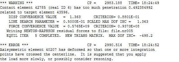 n
September 23, 2020 at 3:54 pmSubscriberThe solution may be helped by softening the contact. Under the Contact Details, there is a line called Normal Contact Stiffness. Change that from Program Controlled to Factor and change the Factor from 1 to 0.1 or 0.001 and see if that helps.nAnother suggestion is the remove the sharp corner where contact is made and put a small blend radius on that corner. That way you can have many small elements around the contact point.n
n
September 23, 2020 at 3:54 pmSubscriberThe solution may be helped by softening the contact. Under the Contact Details, there is a line called Normal Contact Stiffness. Change that from Program Controlled to Factor and change the Factor from 1 to 0.1 or 0.001 and see if that helps.nAnother suggestion is the remove the sharp corner where contact is made and put a small blend radius on that corner. That way you can have many small elements around the contact point.n n
September 24, 2020 at 1:38 pmSubscriberThanks alot for all the suggestion. Solution got converged!nOctober 26, 2020 at 6:38 amSubscriberHi nWhen I ran my full Simulation I got the result with some warning and no error. In result I have equivalent stress (Von mises stress) around 3 times more than Yield and Ulimate strength but still there is no fracture seen in the model. How do I get to know the model I created in transient structural is correct.nOctober 26, 2020 at 12:00 pmSubscribernPlease read this discussion and come back with any follow up questions.n/forum/discussion/1373/i-want-to-see-the-failure/p1nNovember 25, 2020 at 6:21 amSubscriberHi PeternI have gone through the attached link. I got the point explained.nnNovember 25, 2020 at 6:34 amSubscriberI have doubt when I tried to create model in the static structural I was not able to get the converge solution I used to get error solver was unable to converge the nonlinear problem . When I shifted to Transient Structural module I got the Converged solution even though my problem was static. Is it because the Transient Structural uses Full newton Raphson Method? like how do we decide the Static or Transient module to be used. Can you please give some tips/ example.nNovember 25, 2020 at 5:42 pmSubscribernOne type of problem that is difficult to solve with Static Structural analysis that is easier to solve in Transient Structural (or Explicit Dynamics) is snap-through behavior. This occurs when a structure buckles into a new shape. It is difficult for the Static solver to increment the load gradually and remain in static equilibrium to get to the buckled state. But a Transient solver can solve the dynamic equilibrium by including the inertial forces that arise from accelerating the mass to snap-through to the buckled state.nSo the key difference is what type of equilibrium is the solver trying to converge on, static equilibrium or dynamic equilibrium.nNovember 26, 2020 at 10:34 amSubscriberThanks for Explanation. nNovember 26, 2020 at 11:24 amSubscriber
n
September 24, 2020 at 1:38 pmSubscriberThanks alot for all the suggestion. Solution got converged!nOctober 26, 2020 at 6:38 amSubscriberHi nWhen I ran my full Simulation I got the result with some warning and no error. In result I have equivalent stress (Von mises stress) around 3 times more than Yield and Ulimate strength but still there is no fracture seen in the model. How do I get to know the model I created in transient structural is correct.nOctober 26, 2020 at 12:00 pmSubscribernPlease read this discussion and come back with any follow up questions.n/forum/discussion/1373/i-want-to-see-the-failure/p1nNovember 25, 2020 at 6:21 amSubscriberHi PeternI have gone through the attached link. I got the point explained.nnNovember 25, 2020 at 6:34 amSubscriberI have doubt when I tried to create model in the static structural I was not able to get the converge solution I used to get error solver was unable to converge the nonlinear problem . When I shifted to Transient Structural module I got the Converged solution even though my problem was static. Is it because the Transient Structural uses Full newton Raphson Method? like how do we decide the Static or Transient module to be used. Can you please give some tips/ example.nNovember 25, 2020 at 5:42 pmSubscribernOne type of problem that is difficult to solve with Static Structural analysis that is easier to solve in Transient Structural (or Explicit Dynamics) is snap-through behavior. This occurs when a structure buckles into a new shape. It is difficult for the Static solver to increment the load gradually and remain in static equilibrium to get to the buckled state. But a Transient solver can solve the dynamic equilibrium by including the inertial forces that arise from accelerating the mass to snap-through to the buckled state.nSo the key difference is what type of equilibrium is the solver trying to converge on, static equilibrium or dynamic equilibrium.nNovember 26, 2020 at 10:34 amSubscriberThanks for Explanation. nNovember 26, 2020 at 11:24 amSubscriber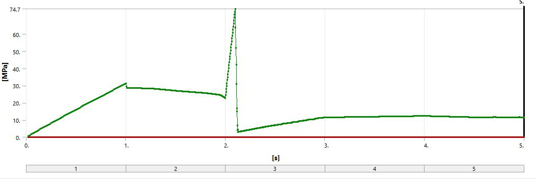 Can you please suggest what and all condition can lead to sudden drop in contact pressure as seen in attached image in 3rd step. In 3rd step differential pressure is applied on the C component between the plate. I have been changing the numerical damping value in Analysis setting to check Impact load issue while differential pressure is applied. Also tried by varying stabilization damping factor in contact controls it didn't help much.n
November 26, 2020 at 4:14 pmSubscriberNumerical damping stabilizes the numerical integration scheme by damping out the unwanted high frequency modes. You should not need to change this value. You need Structural Damping. Structural damping refers to physical damping present in the system. For more information, see Damping in the Structural Analysis Guide. nThe contact pressure could make a sudden reduction if the deformation in the C changes from one node in contact at the tip to several nodes in contact on the side.nDecember 2, 2020 at 6:15 amSubscriberThanks for the explanation.nDecember 2, 2020 at 6:27 amSubscriberIn 2D Axisymmetric analysis I'm not able to define rigid-deformable contact. In geometry when I try to define stiffness behavior as flexible to C and rigid to the 2 side plates. It does'nt take. So I'm able to define only deformable-deformable contact with flexible stiffness behavior. Is there any other way to change the contact definition.n
Can you please suggest what and all condition can lead to sudden drop in contact pressure as seen in attached image in 3rd step. In 3rd step differential pressure is applied on the C component between the plate. I have been changing the numerical damping value in Analysis setting to check Impact load issue while differential pressure is applied. Also tried by varying stabilization damping factor in contact controls it didn't help much.n
November 26, 2020 at 4:14 pmSubscriberNumerical damping stabilizes the numerical integration scheme by damping out the unwanted high frequency modes. You should not need to change this value. You need Structural Damping. Structural damping refers to physical damping present in the system. For more information, see Damping in the Structural Analysis Guide. nThe contact pressure could make a sudden reduction if the deformation in the C changes from one node in contact at the tip to several nodes in contact on the side.nDecember 2, 2020 at 6:15 amSubscriberThanks for the explanation.nDecember 2, 2020 at 6:27 amSubscriberIn 2D Axisymmetric analysis I'm not able to define rigid-deformable contact. In geometry when I try to define stiffness behavior as flexible to C and rigid to the 2 side plates. It does'nt take. So I'm able to define only deformable-deformable contact with flexible stiffness behavior. Is there any other way to change the contact definition.n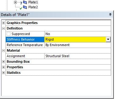 n
December 6, 2020 at 2:28 amSubscribernYou can't define the Stiffness Behavior of the body to be Rigid in a 2D Axisymmetric model.nBut you can pick that face/body, and assign a Displacement BC to both X and Y coordinates, which makes the body behave like a rigid body.nDecember 6, 2020 at 2:32 amSubscribernDecember 7, 2020 at 5:26 amSubscriberThanks , Peter!nI have done the same as you have described. Can you please explain reason why the stiffness behavior can't be rigid/ any source from where I can get information, and how can I define the rigid-flexible contact in my model is there any other way?nDecember 8, 2020 at 5:23 amSubscriberThanks Peter!nI have done the same as you explain to define the body rigid. Can you please explain the reason why stiffness behavior can't be define/ any source from where I can understand the reason. Is there any other way to define the rigid-deformable contact in 2D Axisymmetric model?nDecember 9, 2020 at 1:56 amSubscribernI don't know why you can't have a body in an axisymmetric analysis be rigid for use in contact. As I suggested, if you put all the nodes of a body in a Displacement BC that sets both X and Y, that is the same as being rigid.nDecember 10, 2020 at 6:23 amSubscriberYes I have done the same as you suggested. nThank you.nDecember 10, 2020 at 6:32 amSubscriberI have one doubt, In Plane stress/ strain analysis I want to define revolute joint, but I see that no joint is applicable for 2D analysis. Is there any specific reason for the this. How can we define joints for plane stress/strain case.nDecember 10, 2020 at 5:12 pmSubscribernIn an axisymmetric model, a revolute joint doesn't make sense.nIn a Plane Stress/Strain 2D analysis, you can get the effect of a revolute joint to ground by fixing a vertex in X and Y, which leaves rotation about Z free. That puts a lot of stress on that vertex. If you use a Remote Displacement, you can spread the stress over the length of one or more edges, and set X and Y to 0 while leaving rotation about Z free.nJoints in Mechanical are an easy-to-use GUI that creates MPC APDL code behind the front end. I don't know why they are turned off in 2D models. Read the ANSYS Help system to learn how to construct a revolute joint using APDL code and if there are any limitations for 2D analysis.nDecember 17, 2020 at 10:09 amSubscriberThanks Peter.nRemote displacement thing worked.nDecember 28, 2020 at 9:37 amSubscriberHi Peter,nThe C component is sliding out of plate when 95% of simulation is done. Initial contact condition is closed. The previous discussed Boundary condition got solved in new BC I'm facing sliding issue. nnnDecember 28, 2020 at 9:49 amDecember 28, 2020 at 1:09 pmSubscribernThere is not enough information to provide guidance.nPlease attach the .wbpz Project Archive file so I can take a look.nnDecember 30, 2020 at 10:25 amSubscribernDecember 30, 2020 at 2:23 pmSubscribernWhat version of ANSYS are you using?nWhy are you using Transient? Why not Static Structural?nYour material includes a Norton Creep model but your simulation time is 3 seconds. Is it important to model creep in this simulation? If so, the creep constants do not have any temperature dependency. Young's Modulus does have temperature dependency and the thermal condition is quite severe.nHave you considered using Symmetry? Do you expect a symmetric solution?nDecember 30, 2020 at 6:06 pmSubscriberHere is the results up to 1.9 out of the 3 load steps when solving as a statics problem. You can see how, at the end, the frictional interface and the two point contact makes for an unstable stick-slip motion.nIf you imposed a symmetry condition, that would make it easier to converge.nDecember 31, 2020 at 5:27 amSubscriberThanks Peter.nI'm using Ansys 16.2 version.nI have tried static structural with other model it was not converging. So I shifted to Transient and got converged solution.nBut in this model there is sliding issue. nModeling creep is not important here.nI expect symmetric solution.nnDecember 31, 2020 at 6:24 pmSubscribernOkay, delete Norton from the material model. Slice the ring in half and impose a Y = 0 constraint on that cut boundary to create the symmetry condition. Now you only need one plate to push on the ring.nJanuary 7, 2021 at 11:11 amSubscriberThanks Peter.nI have tried symmetry condition it worked out. nDecember 26, 2022 at 8:54 pm
n
December 6, 2020 at 2:28 amSubscribernYou can't define the Stiffness Behavior of the body to be Rigid in a 2D Axisymmetric model.nBut you can pick that face/body, and assign a Displacement BC to both X and Y coordinates, which makes the body behave like a rigid body.nDecember 6, 2020 at 2:32 amSubscribernDecember 7, 2020 at 5:26 amSubscriberThanks , Peter!nI have done the same as you have described. Can you please explain reason why the stiffness behavior can't be rigid/ any source from where I can get information, and how can I define the rigid-flexible contact in my model is there any other way?nDecember 8, 2020 at 5:23 amSubscriberThanks Peter!nI have done the same as you explain to define the body rigid. Can you please explain the reason why stiffness behavior can't be define/ any source from where I can understand the reason. Is there any other way to define the rigid-deformable contact in 2D Axisymmetric model?nDecember 9, 2020 at 1:56 amSubscribernI don't know why you can't have a body in an axisymmetric analysis be rigid for use in contact. As I suggested, if you put all the nodes of a body in a Displacement BC that sets both X and Y, that is the same as being rigid.nDecember 10, 2020 at 6:23 amSubscriberYes I have done the same as you suggested. nThank you.nDecember 10, 2020 at 6:32 amSubscriberI have one doubt, In Plane stress/ strain analysis I want to define revolute joint, but I see that no joint is applicable for 2D analysis. Is there any specific reason for the this. How can we define joints for plane stress/strain case.nDecember 10, 2020 at 5:12 pmSubscribernIn an axisymmetric model, a revolute joint doesn't make sense.nIn a Plane Stress/Strain 2D analysis, you can get the effect of a revolute joint to ground by fixing a vertex in X and Y, which leaves rotation about Z free. That puts a lot of stress on that vertex. If you use a Remote Displacement, you can spread the stress over the length of one or more edges, and set X and Y to 0 while leaving rotation about Z free.nJoints in Mechanical are an easy-to-use GUI that creates MPC APDL code behind the front end. I don't know why they are turned off in 2D models. Read the ANSYS Help system to learn how to construct a revolute joint using APDL code and if there are any limitations for 2D analysis.nDecember 17, 2020 at 10:09 amSubscriberThanks Peter.nRemote displacement thing worked.nDecember 28, 2020 at 9:37 amSubscriberHi Peter,nThe C component is sliding out of plate when 95% of simulation is done. Initial contact condition is closed. The previous discussed Boundary condition got solved in new BC I'm facing sliding issue. nnnDecember 28, 2020 at 9:49 amDecember 28, 2020 at 1:09 pmSubscribernThere is not enough information to provide guidance.nPlease attach the .wbpz Project Archive file so I can take a look.nnDecember 30, 2020 at 10:25 amSubscribernDecember 30, 2020 at 2:23 pmSubscribernWhat version of ANSYS are you using?nWhy are you using Transient? Why not Static Structural?nYour material includes a Norton Creep model but your simulation time is 3 seconds. Is it important to model creep in this simulation? If so, the creep constants do not have any temperature dependency. Young's Modulus does have temperature dependency and the thermal condition is quite severe.nHave you considered using Symmetry? Do you expect a symmetric solution?nDecember 30, 2020 at 6:06 pmSubscriberHere is the results up to 1.9 out of the 3 load steps when solving as a statics problem. You can see how, at the end, the frictional interface and the two point contact makes for an unstable stick-slip motion.nIf you imposed a symmetry condition, that would make it easier to converge.nDecember 31, 2020 at 5:27 amSubscriberThanks Peter.nI'm using Ansys 16.2 version.nI have tried static structural with other model it was not converging. So I shifted to Transient and got converged solution.nBut in this model there is sliding issue. nModeling creep is not important here.nI expect symmetric solution.nnDecember 31, 2020 at 6:24 pmSubscribernOkay, delete Norton from the material model. Slice the ring in half and impose a Y = 0 constraint on that cut boundary to create the symmetry condition. Now you only need one plate to push on the ring.nJanuary 7, 2021 at 11:11 amSubscriberThanks Peter.nI have tried symmetry condition it worked out. nDecember 26, 2022 at 8:54 pmAli Kamali
SubscriberViewing 37 reply threads- The topic ‘Convergence issue in non linear problem’ is closed to new replies.
Ansys Innovation Space Trending discussions
 Top Contributors
-
peteroznewman
 3597
3597 -
scabo
 1258
1258 -
Dennis Chen
 1107
1107 -
javat33489
 1068
1068 -
Shyam Prasad V Atri
953
Top Rated Tags
© 2025 Copyright ANSYS, Inc. All rights reserved.
Ansys does not support the usage of unauthorized Ansys software. Please visit www.ansys.com to obtain an official distribution.
-


The Ansys Learning Forum is a public forum. You are prohibited from providing (i) information that is confidential to You, your employer, or any third party, (ii) Personal Data or individually identifiable health information, (iii) any information that is U.S. Government Classified, Controlled Unclassified Information, International Traffic in Arms Regulators (ITAR) or Export Administration Regulators (EAR) controlled or otherwise have been determined by the United States Government or by a foreign government to require protection against unauthorized disclosure for reasons of national security, or (iv) topics or information restricted by the People's Republic of China data protection and privacy laws.


