TAGGED: Dielectric, Lumerical-FDTD, metasurface, photonics, Resonances, Vector-plot
-
-
September 10, 2024 at 3:40 pm
pm796
SubscriberI posted this question/issue previously and for some reason it was marked as 'closed' despite there being no replies (and it is a photonics question). Thanks in advance for any insightful replies!
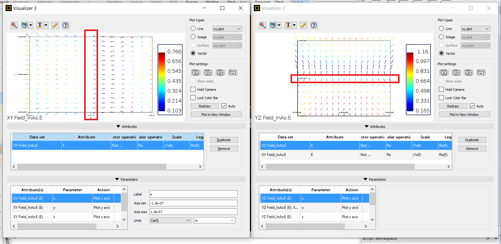
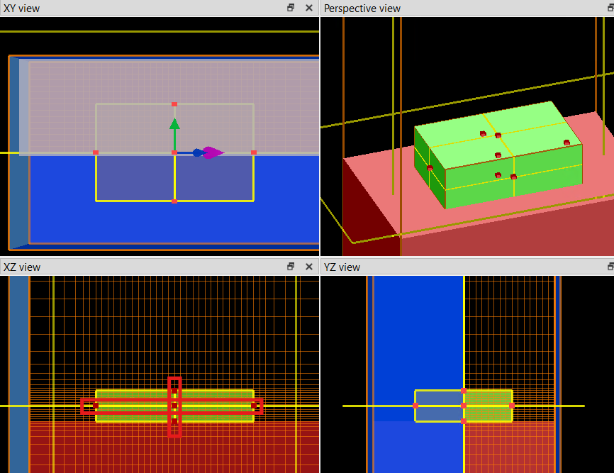
I am running a simulation in a cuboid. The XYZ origin is at the centroid of the cuboid. I have two FD monitors, one in the XY plane (plan view) and one one in the YZ (end) plane, both passing through the origin (as highlighted in the red boxes on the green cuboid in the bottom left panel of screenshot 2 below). Looking at the point where the two orthogonal planes intersect (highlighted by red boxes on the screenshots), I am confused as to why at the point where the two slices intersect, the XY results clearly show the E field vectors diverging through the boundaries, but the YZ shows the field vectors at the same point converging. Does anyone know what is happening here, am I missing something?
As an aside, does anyone know if there is any more information on how to interpret results, units, etc in the 'visualiser' panes? The 'reference manual' is quite lacking. Also, the font on the chart in the visualiser is unreadably small - is there any way to change that?
Thanks for your help!
Phil
-
September 11, 2024 at 6:44 pm
Guilin Sun
Ansys EmployeeThis is duplicated from this What is happening with the vector E fields in this simulation? (ansys.com) and it will be closed. Please continue on the other post.
Later on if one post is not answered on time, no need to write a new post. Instead, just reply the previous post to either give more information or simply write a sentence to make us aware of it.
-
- The topic ‘Contradictory E field vectors in orthogonal planes’ is closed to new replies.


-
4673
-
1565
-
1386
-
1231
-
1021

© 2025 Copyright ANSYS, Inc. All rights reserved.


