
-
-
September 17, 2021 at 5:53 pm
sblee
SubscriberI am working on contact analysis between a plate and a semi-ball. I encountered "solver pivot warnings or errors due to ill conditioned matrix." Project archive attached for your review.
September 18, 2021 at 1:57 ampeteroznewman
SubscriberThe solver pivot warnings are because there are no constraints holding the plate. Follow the directions below to create a 1/4 symmetry model that, along with frictional contact, will completely support the plate.
Don't use Bonded Contact, change it to Frictional Contact.
Open the Geometry editor and move the ball to be tangent to the plate.
In the Geometry editor, make two planes through the center of the ball to cut the ball and plate into four pieces each. Delete 3 of each to have a quarter symmetry model.
In Mechancial, Add a Displacement for the two cut faces whose normals are aligned with the X axis and set X = 0 leaving Y and Z free. Add a Displacement for the two cut faces whose normals are aligned with the Z axis and set Z = 0 leaving Y and X free. Those are your two symmetry boundary conditions.
Edit the force to be 6/4 = 1.5 N since you have a 1/4 symmetry model.
Right click on the Connections folder and insert a Contact Tool. Right click on it and Generate Initial Contact Status. Look at the status results and check that the Frictional contact is Closed. If it is not, edit the contact and change the Interface Treatment to Adjust to Touch.
Click on Analysis Settings and change Large Deflection to On.
Solve. If it does not converge. Come back for more instructions.
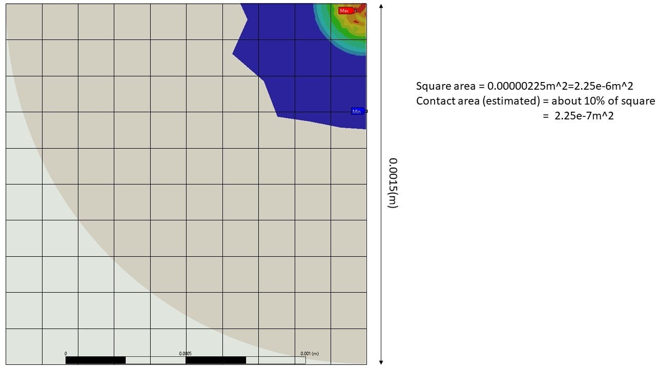
If it solved, under the Solution branch, insert a Contact tool. Right click on the contact tool and insert a Pressure result. Now you can see which elements have a pressure to help you estimate 1/4 of the contact area.
September 28, 2021 at 2:42 pmSubscriberThank you @peteroznewman! Can you try attached? I tried to make all the changes as you mentioned and made it work!
But I am still in trouble as below:
1) When force is changed (larger) from currently 1.5N, it does not solve (2.5N, for ex). I want to study the change of contact area by the change of force.
2) Mesh refinement actually does not help, but it generates errors also. The error message says I need to increase number of substeps or decrease the time step. Where/how can I do?
3) How can I get a exact contact area using APDL command under "solution" in the menu tree. Can you help if it writes ok (currently it does not work)?
Thanks.
September 29, 2021 at 3:55 amSubscriberDon't use 10 steps, use 1 step, then add a second step to add more force. I set the force to be -1.5 in step 1 and -2.4 N in step 2. Turn on Auto Time Stepping. This lets you define substeps. I used an Initial and Minimum Substep of 10 and a Maximum Substep of 1000.
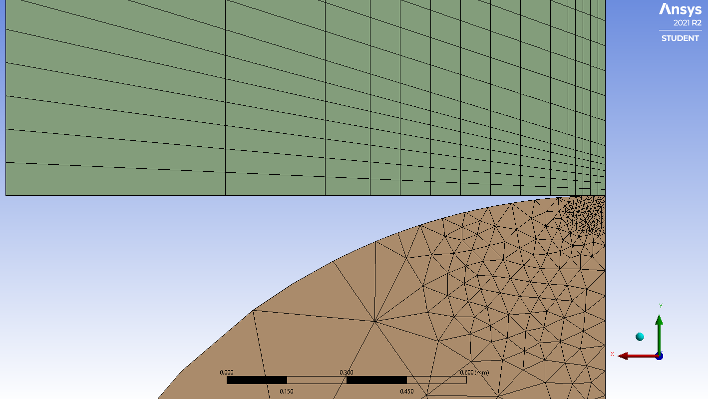
Try using a coarser mesh. The mesh below was made with two Body Sizing controls that used Sphere of Influence. That required a Coordinate System to be created at the vertex. A coarser mesh will also make the solution compute much faster. With those changes, I had no problem converging with 2.4 N of load.
Add Penetration to the Contact Tool in the Solution branch. The mesh I used had a penetration of 0.0052 mm with 2.4 N of load. If this seems too large, then you can edit the Contact definition and change the Formulation to Normal Lagrange. This is going to increase the number of iterations the solver has to do, so the solution will take longer and can make convergence more difficult. So don't make that change unless you need to.
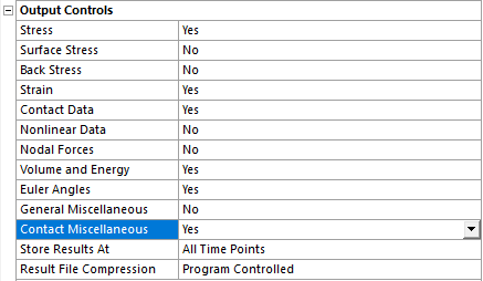
To get your code to work, you just need to change the Output Controls under the Analysis Settings to say Yes to Contact Misc.
 Are you only interested in applying force low enough to stay in the elastic range of the materials? Most materials have a yield strength. When the stress exceeds the yield strength, the material will flow and become permanently deformed. You are only using linear elastic material properties, so the material cannot yield and any results with stress above the yield strength are non-physical.
In Workbench, click on Engineering Data, and under the Plasticity category are many material models. The simplest is Bilinear Kinematic Hardening. Add that to your materials. Now you can insert the Yield Strength and Tangent Modulus. Try a value of 0 for Tangent Modulus.
September 29, 2021 at 8:02 pmSubscriberGreat! Mesh size was adjusted as advised, and the analysis is faster than before. Thank you.
1) I changed "the Output Controls under the Analysis Settings to say Yes to Contact Misc," but I could not get the area values using "commands (APDL)" or CONTPENE menu. Could you take a look the attached?
2) Is your graph (the last figure) for depth (mm) or area?
3) I am interested in linear analysis only, so there is no yield.
Thank you.
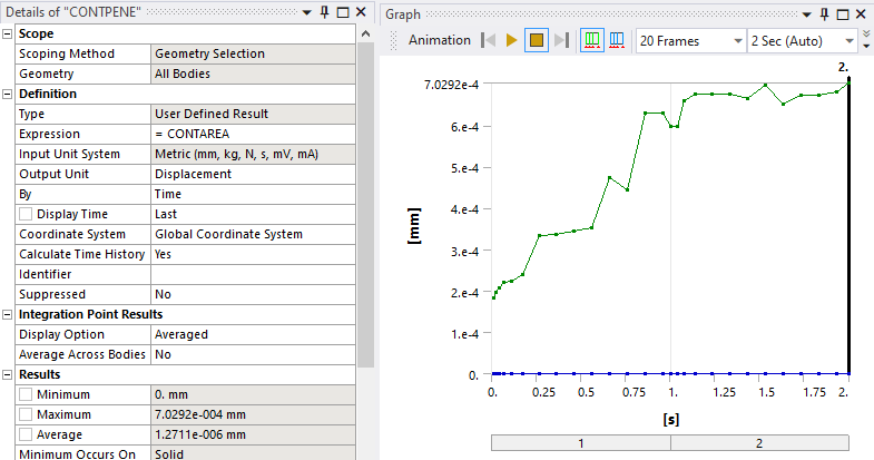
September 29, 2021 at 10:14 pmSubscriberWhat version of Ansys are you using? The graph was the output of CONTPENE with the expression CONTAREA. I just downloaded and ran your model and I get a graph.
 September 30, 2021 at 2:49 amSubscriberOk, I use 2021R2 and I could get the same plot. Thanks.
But I want to figure out the contact area (as number). I could get three different numbers from
1) CONPETE = 3.1826e-006 m (displacement dimension)
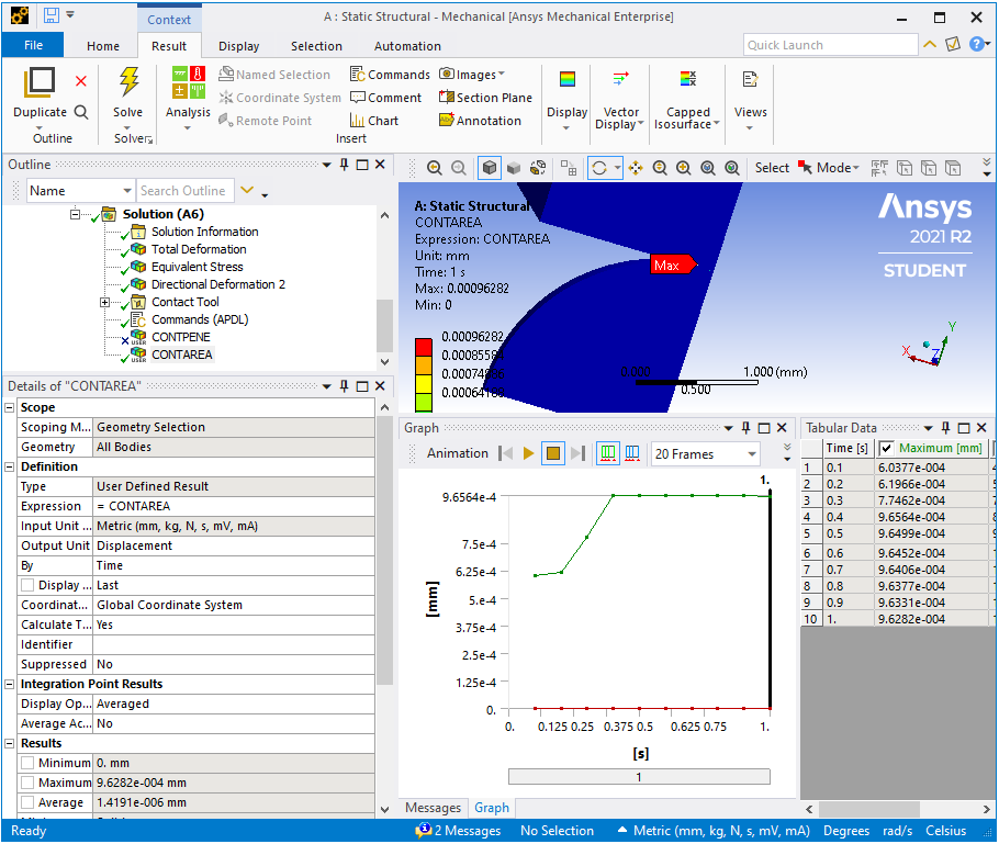
2) CONAREA = 9.6282e-007 m (displacement dimension)
3) command (APDL) = 4.1898e-008 (probably m^2)
But none of them looks close to my estimation from "pressure" contour (as you answered to my first posting) which is 2.25e-7 (m^2) - see attached.
Any thought to get an exact number for
contact area? Really appreciate it!
October 6, 2021 at 3:33 pmSubscriberHello, any help to my inquiry is greatly appreciated! Please advise. Thanks.
Viewing 7 reply threads- The topic ‘contact analysis issue’ is closed to new replies.
Innovation Space Trending discussions
 Top Contributors
-
peteroznewman
 5824
5824 -
scabo
 1906
1906 -
Dennis Chen
 1420
1420 -
javat33489
 1305
1305 -
Shyam Prasad V Atri
1021
Top Rated Tags
© 2026 Copyright ANSYS, Inc. All rights reserved.
Ansys does not support the usage of unauthorized Ansys software. Please visit www.ansys.com to obtain an official distribution.
-


The Ansys Learning Forum is a public forum. You are prohibited from providing (i) information that is confidential to You, your employer, or any third party, (ii) Personal Data or individually identifiable health information, (iii) any information that is U.S. Government Classified, Controlled Unclassified Information, International Traffic in Arms Regulators (ITAR) or Export Administration Regulators (EAR) controlled or otherwise have been determined by the United States Government or by a foreign government to require protection against unauthorized disclosure for reasons of national security, or (iv) topics or information restricted by the People's Republic of China data protection and privacy laws.
