-
-
April 21, 2019 at 10:01 pm
yang
SubscriberHi all, as the figure below, I was simulating a roof. It consists of cables and shells. The cable is simulated by Link180 and only tension is allowed. The shell is simulated by Shell 181.
This indicates that there are moments in shell elements but no moments in Link elements. Is it possible to release the rotational degree of freedom along the edge of the shell? Any thoughts? Thanks.
-
April 22, 2019 at 2:57 am
peteroznewman
SubscriberOn a SHELL181, set KEYOPT(1) = 1 to get Membrane stiffness only. If the membrane option is used, the element has translational degrees of freedom only.
The default element stiffness is Bending and membrane stiffness.
-
April 22, 2019 at 6:47 am
jj77
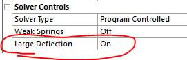
SubscriberI agree with Peter, if this is a fabric or membarne structure then use membrane elements - remember for membrane structures that NLGEM,ON should be used.
-
April 22, 2019 at 4:43 pm
yang
SubscriberHello Peter. Thank you for your suggestion! It's very helpful. Another question here. If the membrane option is used, should pretension (or initial state) be defined? If so, how could I pretension the shell element?
-
April 22, 2019 at 4:47 pm
-
April 22, 2019 at 5:28 pm
jj77
SubscriberYes, typically for membrane structures (tent like fabric structures say), one needs large deflections active/on since for wind loads (shell out of plane loads) one needs to built up bending stiffness via membrane actions (stress stiffening), and that is a nonlinear effect.
Â
Tried this once with the inistate command and it seems to work: see some posts on that for truss elements which is the 1D version of a membrane (in the INIS,DEFINE seen in this link and additional strain value is given for the other direction, thus both plate/shell x and local y stress/strains need to be assigned to a membrane while in a truss only one is given say local x - thus for a membrane it would be:
INIS,SET,CSYS,-2Â Â Â
INIS,SET,DTYP,EPEL
INIS,DEFINE,,,,,1.5E-5,1.5E-5Â ! strain in both local x and y directions of the plate, unit less).
/forum/forums/topic/tranmission-tower-cable-simulation-in-ansys-workbench/
Â
One can also apply an initial membrane load and ones there is some out of plane stiffness, apply the out of plane loads (e.g., wind)
Â
-
April 22, 2019 at 9:26 pm
yang
SubscriberHello jj77,
Â
Thank you for providing the info. I appreciate it. I followed your instructions. The line body is simulated by Link180 with tension only with the following command:
et, 1,link180
SECTYPE,1,LINK
SECDATA,9.7e-5
SECCONTROL,,1
Â
It is prestressed with the following command:
INIS,SET,CSYS,-2
inistate,set,dtyp,stre
inistate,define,,,,,0.5e8
Â
The shells are modeled by shell 181 with membrane stresses only, achieved by the following command:
et,23,SHELL181,1
It is prestressed with the following command:
INIS,SET,CSYS,-2
inistate,set,dtyp,stre
inistate,define,,,,,0.01e8
Â
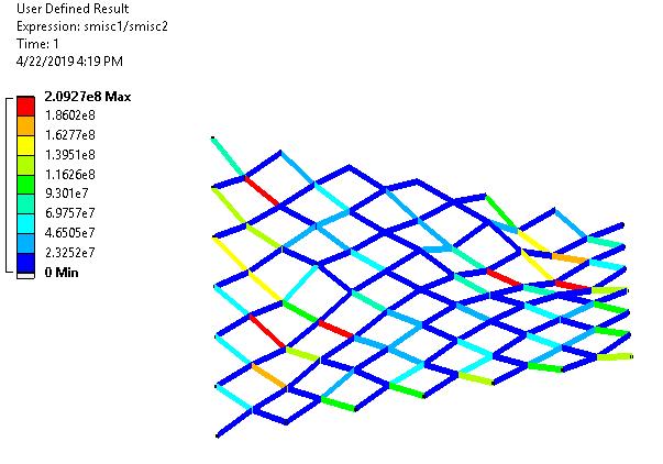
I add standard earth gravity and pressure on the shell surface, and conduct static analysis. But I got zero tension force in the Link180. Do you happen to know why? If there is zero tension force, the cables are not stable. Thanks again.
Â
Â
-
- The topic ‘connection between shell element and Link element’ is closed to new replies.

-
6515
-
1906
-
1463
-
1308
-
1022
© 2026 Copyright ANSYS, Inc. All rights reserved.