Ansys Assistant will be unavailable on the Learning Forum starting January 30. An upgraded version is coming soon. We apologize for any inconvenience and appreciate your patience. Stay tuned for updates.
Fluids

Fluids

Topics related to Fluent, CFX, Turbogrid and more.

conformal cooling in Fluent

    • Jackely
      Subscriber

      I've been working on conformal cooling channels for weeks.
      I started with Steady State Thermal to understand the problem better (see link).
      and now I'm trying this in Fluent with a given speed.
      i don't get along with Fluent yet, i have seen couples tutorials.
      I do not see any temperature distribution in the component.
      I think something is wrong with Boundary Conditions!


      in this tool are 2 channels where plastic (200 °C) and water (40 °C) flows through.


    • Rob
      Forum Moderator

      Please post screen grabs of the thermal tab of the wall that separates the liquid & solid.

    • Jackely
      Subscriber

       Many thanks for your answer
      I see now that that wall is deifying as Coupled.


      shall I define the heat generation rate?


      I have 4 walls in total!


    • Jackely
      Subscriber

      I modified the boundary conditions and created a new geometry.
      I've activated three models: Multiphase, Energy and Viscous k-epsilon.
      a heat flux density of 50 000 W/m^2 flows along the wall.


      But the result does not look realistic (see last picture).


    • DrAmine
      Ansys Employee

      Are you doing the full run in Fluent? Or are you coupling to structural/thermal?

    • Jackely
      Subscriber

      i do full run at Fluent. into canal flows water by speed of 2m/s and 40°C and upside at wall affects heat flux density of 5 w/cm^2


    • DrAmine
      Ansys Employee

      Okay so water is located in that cylindrical part. If you want to visualize the temperature at the solids you need to use Static Temperature. Total Temperature is only defined for Fluids.


      Start at first without multiphase: just check if your setup makes sense.

    • DrAmine
      Ansys Employee

      Moving to the Fluid Dynamics Category.

    • Jackely
      Subscriber

      Thanks for your answer.


       i have now only activated the energy and k-e for Models


      I have researched the internet, and most of them say that the problem could be with the interface.
      i have defined the two interfaces as a wall (Coupled).


      The results are still not realistic.


    • DrAmine
      Ansys Employee
      But you do not have interfaces you have interior cells. Please do not change that type. Please show mesh lines to check if the mesh is conformal
    • DrAmine
      Ansys Employee
      Please go to Flux Flux report and screenshot total heat transfer there as well as mass flow rates.
    • Jackely
      Subscriber

      That's right, I don't have an interface.
      these are the pictures


    • DrAmine
      Ansys Employee
      And what does now the Flux report tell u?
    • Jackely
      Subscriber

      the mass flow stays constant between inlet and outlet and this is realistic, other components are 0 because they are solid and do not move.
      the heat flow at outlet is bigger than at inlet.


      and in components there is no heat flow, but in the layer between water and component yes (- 3,3283 W and 3,324 W)


      what should I do to get the heat flow into the component?

    • DrAmine
      Ansys Employee

      I do not understand. You have a heat flow from solid to fluid so it is working. You can post process the temperature at the wall on the fluid side and its shadow on the solid side.

    • Jackely
      Subscriber

      i have now shown the temperature distribution, the distribution looks relaistic, but the values do not.
      Water temperature should actually only be 40°C.


    • Jackely
      Subscriber

       with CFX The results look different.


    • Jackely
      Subscriber

      Thanks for your tips
      The problem is solved, I defined a surface at Fluid (and called interface)
      and then changed interface to wall and defined as coupled.


    • Whiteney1991
      Subscriber
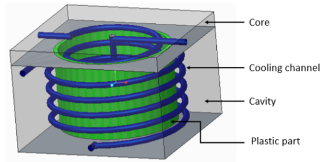
      Figure above courtesy of Suchana et al., 2017. My question is not directly related to this but this seems to be the closest I have come across for CCC simulation in ANSYS. Is it best for me to use ANSYS Transient thermal or ANSYS Fluent to obtain cooling time of the plastic part versus decreasing temperature of the plastic part? Also, how do I apply the boundary conditions given such as Initial temperature of the molten ), simulation time, water coolant, convective thermal coefficient, inlet coolant temperature, plastic initial temperature, mold and plastic properties (density, specific heat and isotropic thermal conductivity and ejection temperature? For example, do I apply the initial plastic temperature on all the surfaces of the plastic part? Do I apply the coolant temperature at the inlet or on the surface of the conformal cooling channels?.Thank youn
    • Rob
      Forum Moderator
      Yes, no, maybe. What do you know re the fluid flow and what do you need to know?
    • Whiteney1991
      Subscriber
      Hi Rob, thank you for responding. The details given by the author for the simulation are as follows.nCOOLANT: Water; Inlet temperature 25 oC both in core and cavity; Convective thermal coefficient is 5352 W/m2K.; Flow ret 4 Litres/minute (considered turbulent flow).nMOLD (core and cavity): 135 mm height, 190 mm width and 200 mm length; Material is structural steel (density 7850Kg/m3, specific heat 434 J/KgK and thermal conductivity of plastic of 60.5 W/mK).nCONFORMAL COOLING CHANNELS (the spiral/helical one in blue in the image): diameter - 8 mm, cross-section - circular, pitch - 20 mm.nPLASTIC PART: Diameter 150mm; height 100mm; thickness 5mm; Flange diameter 190mm; Material - polypropylene (density 830Kg/m3, specific heat 1900 J/KgK and isotropic thermal conductivity of plastic of 0.14 W/mK); Molten plastic initial temperature 168 oC.nMESH: Fine meshing, medium smoothing (automatic mesh generator) - they got 94088 elements and 155,900 nodes.nTIME: Simulation time - 150snSOLUTION: Plastic takes 7.4s to cool down to ejection temperature of 87 oC.nThank you.n
    • Rob
      Forum Moderator
      And what do you want to find out?n
    • Whiteney1991
      Subscriber
      @Rob, I am quite new to ANSYS and would like to know how I will apply those boundary conditions so as to obtain the time taken for the plastic part to attain 87 oC. More specifically:nDo I assign the cooling channels as fluid or as structural steel during simulation?nIs the initial temperature the initial temperature of the molten material i.e.168 oC or room temperature?nApplying convection, is the ambient temperature the inlet temperature of the coolant?nDo I apply the ambient temperature at the inlets or outlets or on the surface of the conformal cooling channels?.Thank you.n
    • Rob
      Forum Moderator
      It depends. If you want to model the flow in the cooling channels: you can do this OR assign a HTC/flux etc and avoid the fluid part. Re the plastic, if it's cooling down I'd suggest patching it in at whatever temperature it's put in the mold at (most likely a fair bit higher than the melting point). nYou really need to figure out what you're trying to find out, and discuss this with your supervisor as they're the one setting the task. n
Viewing 23 reply threads
  • The topic ‘conformal cooling in Fluent’ is closed to new replies.
[bingo_chatbox]