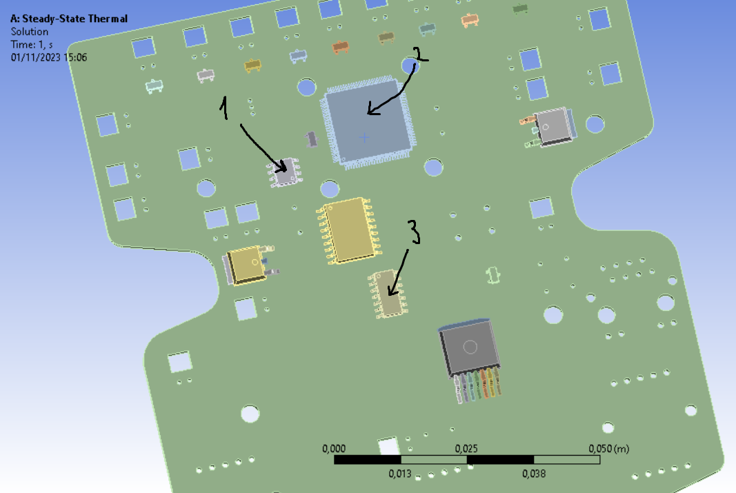
TAGGED: ansys-thermal, pcb, steady-state-thermal
-
-
November 1, 2023 at 2:12 pm
Josep Sucarrats
SubscriberI am new to Ansys, so sorry if I have some misunderstood parts. I am doing a Steady-state Thermal simulation of a PCB with some of its components. I am currently simulating only the highlighted elements in picture 1. They all have the same distance to de PCB (0,05mm between the pins and the PCB, and 0,15mm between the actual IC and the board). As shown in picture 2, components 1 and 3 have a similar behavior: they both are heated more or less the same with the same BC. But if I apply the same BC to component 2 (internal heat generation), it seems not to be connected to the board, as shown in picture 3. How can I fix this issue?
Picture 1:
Picture 2:
Picture 3:
-
November 2, 2023 at 10:51 am
Pdev
Ansys EmployeeHi Josep,
Please file a SR on the customer portal regarding this as we would need to take a look at your model closely. Thanks!
Pdev
-
- The topic ‘Configurating heat transfer between parts’ is closed to new replies.


-
3462
-
1057
-
1051
-
918
-
896

© 2025 Copyright ANSYS, Inc. All rights reserved.


