-
-
July 3, 2023 at 10:29 am
Hemin Sindy
SubscriberHello,
I am modelling a concrete bar under a 4 point bending test with interface delamination. The 2 layers have different properties as they are 2 different concrete like materials. In the bottom layer at midspan a notch is included (
non-frictional contact) to allow the delamination to propagate.
Now the problem is that no matter what I try the behaviour of the concrete beam is not properly simulated, this model is based on a real experiment where delamination results in cracks along the delamination interface in the top layer. Here is an example from the experiment to demonstrate it:

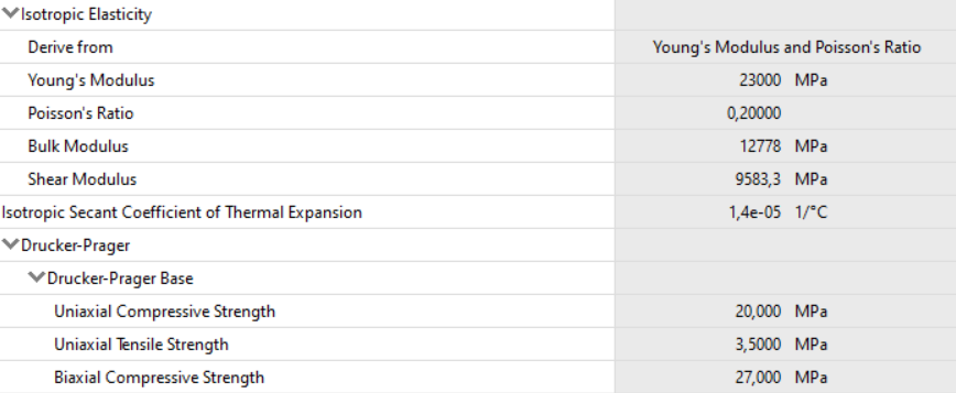
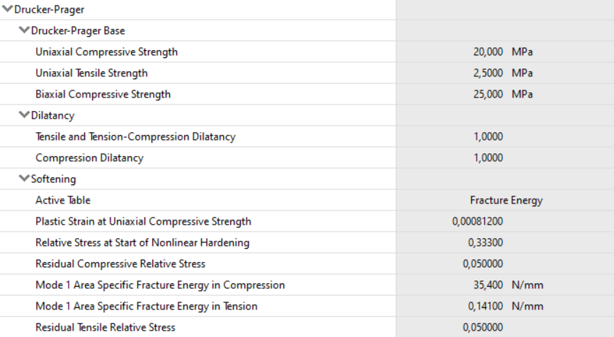
Red indicates the cracks. Now there is no way to properly display cracks in ansys using a static structural analysis (cpt215's damage plot doesn't seem to work in ansys 2022 student version). I am currently looking at principal strains to check whetever there is cracking occuring somewhere. I model the concrete using DP component in workbench (I have tried various things with apdl as well with even worse results):
top layer:
The element type I am currently using is the regular linear solid185. The results I get is the following for EPEL2:

Note that the values of the strain above the delamination surface are simply to low to indicate cracking and this is with an applied load of -5.8 mm (40 kN) instead of the -1.25 mm (14 kN) from the experiment. I also tried to half the compressive strength of concrete which resulted in barely any difference.
It should be noted that I am using the following to model delamination:

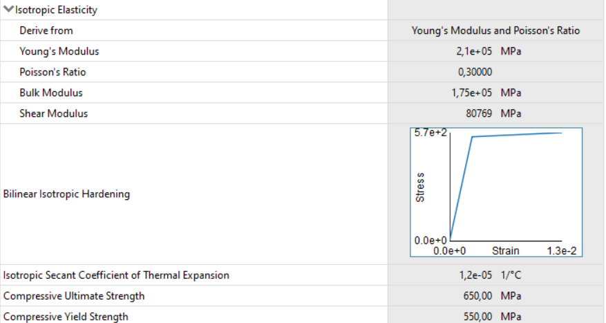
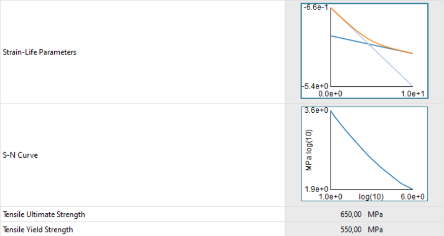
Reinforcement:
If someone can give me advice on how to better model my concrete it would be really appreciated.
I have tried using solid65 before because the element displays crushed and cracked integration points but it has mesh sensitivity and my beam is 1.9 meters long and 0.2 meters high which makes a potentially sufficient mesh size for the analysis incredibly slow to calculate. Even on smaller mesh sizes it tends to not converge for me.
-
July 3, 2023 at 3:33 pm
-
- The topic ‘Concrete modeling with interface delamination’ is closed to new replies.


-
3432
-
1057
-
1051
-
896
-
892

© 2025 Copyright ANSYS, Inc. All rights reserved.


