TAGGED: #Modal_Analysis, psd, random-vibration, static-structural, vibration
-
-
January 7, 2025 at 11:02 amARSubscriber
Hello,
I'm making a model of a motor mount. I need to select dampers or anti-vibration elements at the end of the control and measurement equipment. However, I don't know how to characterize these elements. I have a PSD that would generate the motor so I have done a random vibration, but I don't know what result to extract to characterize the vibration mitigation elements of the instrument bay. What should I use?
-
January 7, 2025 at 12:50 pmpeteroznewmanSubscriber
It's not clear from your brief description if you are trying to design a vibration isolation system, or if you are trying to analyze (characterize) a specific vibration isolation system.
Are you trying to isolate the vibration from the measurement equipment or the ground?
Please expand on the details of your task.
-
January 7, 2025 at 2:13 pmARSubscriber
Hi Peter,
You are right, I have not made myself clear. Right now, I want to design the vibration isolation system to isolate the equipment bay from the rest of the structure vibration. Therefore, I want to extract from the results of the model I have made the necessary data to design a system that eliminates or reduces the vibrations in the equipment. However, I have not designed these systems before. What should I use, the acceleration that the equipment undergoes or what?
-
January 7, 2025 at 10:34 pmpeteroznewmanSubscriber
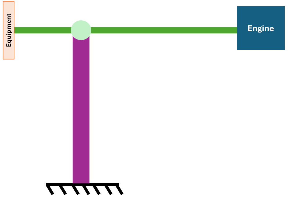
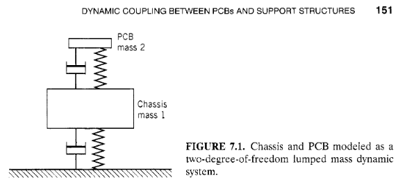
I recommend doing some reading on vibration isolation system design. A good reference textbook that I own is Vibration Analysis for Electronic Equipment by Dave S. Steinberg. Chapter 7 is Octave Rule, Snubbing, and Damping to Increase PCB Fatigue Life. Chapter 9 is Designing Electronics for Random Vibration and 9.23 is the Octave Rule for Random Vibration. Steinberg uses a simplified representation of a chassis and a PCB. These are represented by a spring-damper from the engine frame where the PSD input is present, to the chassis which is represented as a point mass, then another spring-damper from the chassis mass to the point mass that represents the PCB. The chassis is usually going to have more mass than the PCB. Since the chassis mass and PCB mass are connected by the spring-damper connecting them, dynamic coupling occurs.
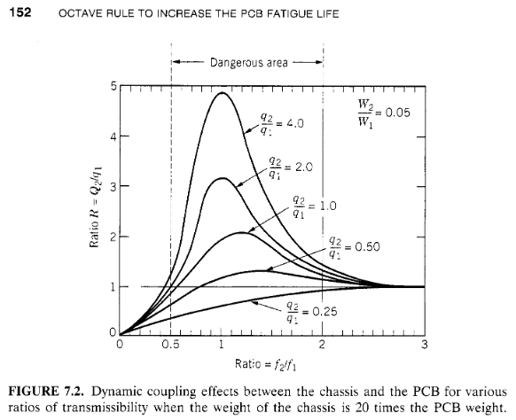
You should build a Modal analysis of the chassis of the measurement equipment box. The bolt holes that connect it to the motor frame become fixed supports. Internally, the lighter and more delicate measurement instruments are connected to features inside the equipment box chassis. Look at the natural frequencies of the structure of the chassis supporting the measurement instruments. Now build a Modal analysis for each of the measurement instruments only. The features that hold each instrument to the chassis become fixed supports. The resulting natural frequencies of the chassis and the various instruments should be separated by more than one octave (a factor of 2) to avoid severe dynamic coupling. For example if the chassis has a natural frequency of 100 Hz, each instrument must have its first natural frequency be greater than 200 Hz. This is called the Forward Octave Rule. You would change the design of the chassis to achieve this result, assuming you don’t design the instruments. When you do that, the PCB is beyond the Dangerous area because the frequency ratio is greater than 2.
Â
-
- You must be logged in to reply to this topic.
- At least one body has been found to have only 1 element in at least 2 directions
- Error when opening saved Workbench project
- How to apply Compression-only Support?
- Geometric stiffness matrix for solid elements
- Frictional No separation contact
- Timestep range set for animation export
- Image to file in Mechanical is bugged and does not show text
- Script Error Code:800a000d
- Elastic limit load, Elastic-plastic limit load
- Element has excessive thickness change, distortion, is turning inside out
-
1406
-
599
-
591
-
555
-
366
© 2025 Copyright ANSYS, Inc. All rights reserved.