-
-
November 20, 2024 at 3:52 am
henry.ojukwu
SubscriberHi everyone,
I need help with a characteristic mode analysis (CMA) of my unit cell.
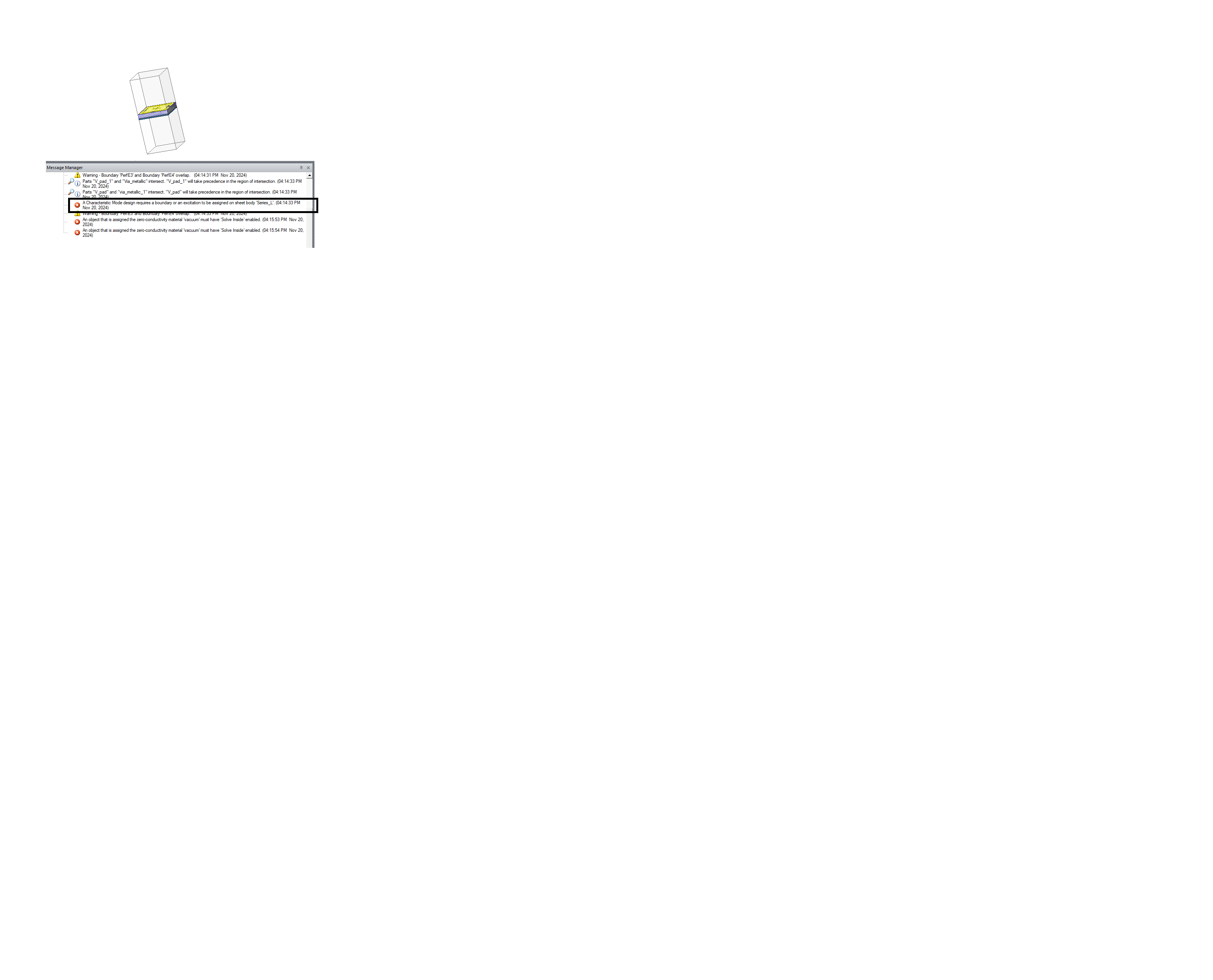
I'm trying to conduct a CMA on my unit cell, but in the CMA solution type in HFSS, I'm unable to assign a boundary condition and Floquet port to the air box surrounding the unit cell. As a result, each time I attempt to run the simulation, I encounter an error message that states, "CMA requires a boundary and excitation."
Could someone please guide me on how to assign the appropriate boundary and excitation to the unit cell in this situation?
Thank you!
-
November 20, 2024 at 11:05 am
Aymen Mzoughi
Ansys EmployeeYou are using the wrong solver. CMA solver is IE based. You should be using HFSS with Hybrid and Arrays solver instead.
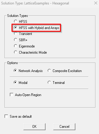
There is an HFSS built-in example of a unit cell that you can take as reference for your setup (File > Open Examples > HFSS > Antennas> phased_array_unitcell.aedt)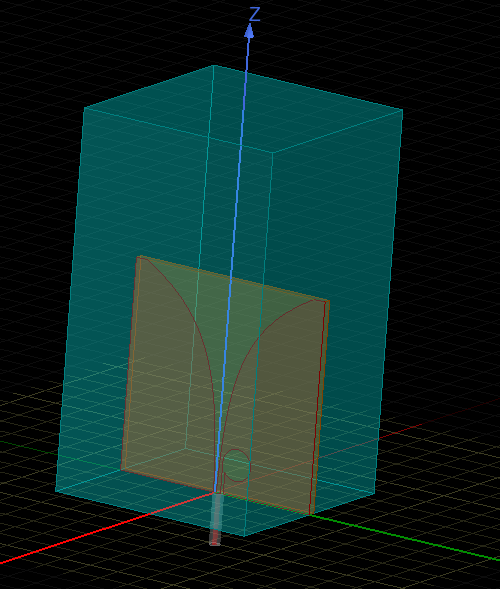
Just a reminder that you may use Ansys Community Feed to develop your network and foster community by joining the appropriate community group and making connections. If you are interested in Electronics content, please join the Electronics group (link - https://innovationspace.ansys.com/community/groups/?electronics-community/) -
November 20, 2024 at 11:10 pm
henry.ojukwu
SubscriberHi Aymen,
Many thanks for your help and guidance.
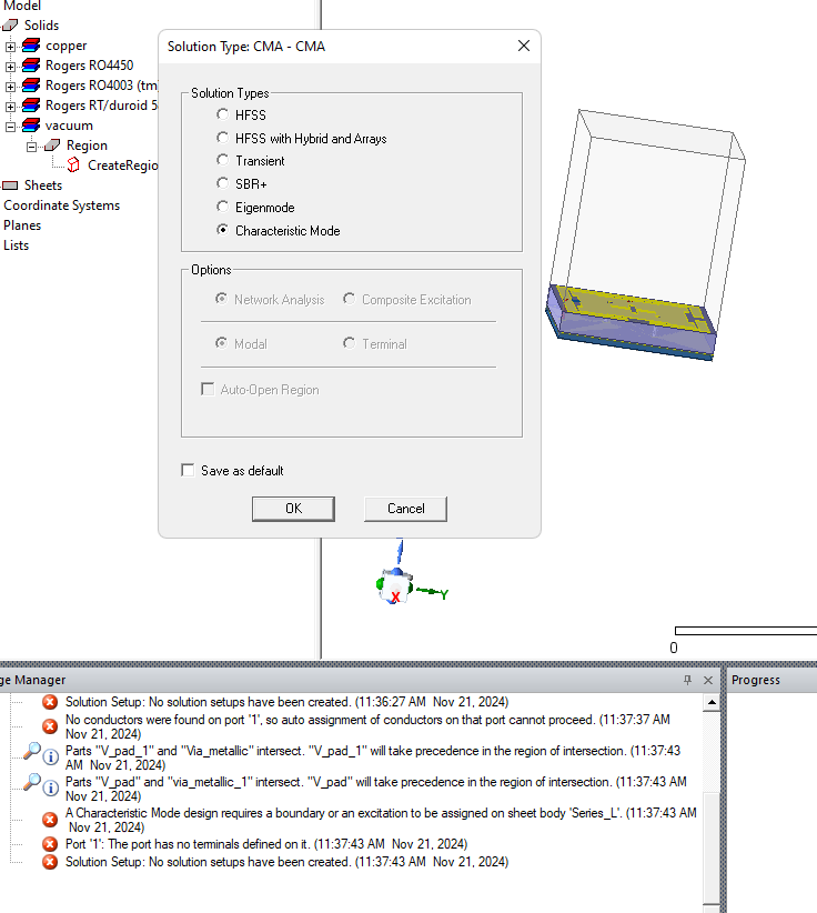
I tried to follow your suggested steps but couldn't achieve the CMA analysis objectives.When you select the "HFSS with Hybrid Array" solution type, as I tried, the option to "Create Characteristic Mode Report" does not appear under the Results tab after the simulation.
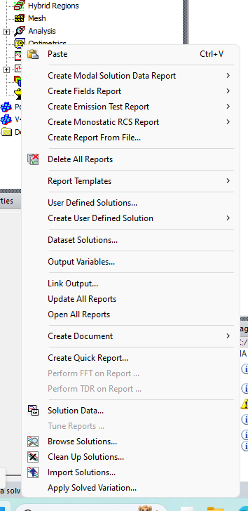
On the other hand, if I choose the Characteristic Mode solution type, I am unable to assign any boundary or excitation type to the air box surrounding the unit cell. And as a result, the simulation fails to run.
Moreover, If I assign a boundary and excitation before switching the solution type to Characteristic Mode, HFSS automatically deletes the existing boundary and excitation settings and displays the following error messages:
1. Boundary 'LatticePair1' and 'LatticePair2' deleted. The boundary type is not allowed when the solution type is Characteristic Mode.
2. Excitation: 'FloquetPort' deleted. No excitations are required when the solution type is Characteristic Mode.Given this, I am not sure what boundary and excitation settings should be used with the Characteristic Mode solution type to successfully analyze the CMA of the unit cell.
Your guidance on this matter would be greatly appreciated.
Henry.
-
- You must be logged in to reply to this topic.


- Polarization and Angle of Incidence Scan with Floquet ports in ANSYS HFSS
- How to create Lumped RLC in HFSS to match Circuit? (Simulate load as Lumped RLC)
- CPW resonant frequency HFSS Simulation
- EMA3D Current Source Problem
- Setting up CPW HFSS Simulation
- Simplorer link to Maxwell transient
- Help on calculating port impedance Zpv using Field calculator under HFSS please
- Question for Maxwell

-
1081
-
447
-
390
-
225
-
201

© 2024 Copyright ANSYS, Inc. All rights reserved.

