-
-
April 23, 2024 at 9:32 am
Oscar Barthel
SubscriberHi,
i am doing some CFD Simulation on Ansys Fluent 2022R2 and want to find out how little changes in the geometry influence the whole flow.
I have 4 zones (3 fluid, 1 solid) and want to change something in the solid part that will probably effect all the fluid zones. I have tried to use the replace zones option for the solid zone, but that produced errors and the programm crashed. The replace mesh option also didnt work.
Does someone have any idea how to solve this problem so i dont have to set up a new case for every little change in the geometry?
Thanks,
Oscar
-
April 23, 2024 at 10:31 am
Rob
Forum ModeratorIf you're changing the solid zone shape won't it also alter the surrounding fluid zones? Reading the complete new mesh into the existing case ought to work, what error messages are showing in the Console?
-
April 23, 2024 at 1:01 pm
Oscar Barthel
Subscriberyes, the geometry change alters every surrounding fluid zone. Reading the new mesh in to the existing case per se works altough i get some notification that surfaces for report definitions cant be found. Initializing also works but when i try to patch one of the fluid zones i get about 20 times the same error:
pop up window:
zone-surface: invalid thread[2]
console:
Error at host: zone-surface: invalid thread[2]
Error at Node 0: zone-surface: invalid thread[2]
Error: zone-surface: invalid thread[2]
Error Object: #f
-
April 23, 2024 at 1:39 pm
Rob
Forum ModeratorHave you got any nonconformal interface zones? Also, check the scale of the new model once the mesh is read in. If the model dimensions are different some of the planes may nolonger exist.
-
April 23, 2024 at 2:40 pm
Oscar Barthel
Subscriberim sorry, but what are nonconformal interface zones?
My change in the geometry was to close two internal boundarys between the fluid zones. Therefore the geometry of some surfaces was changed.
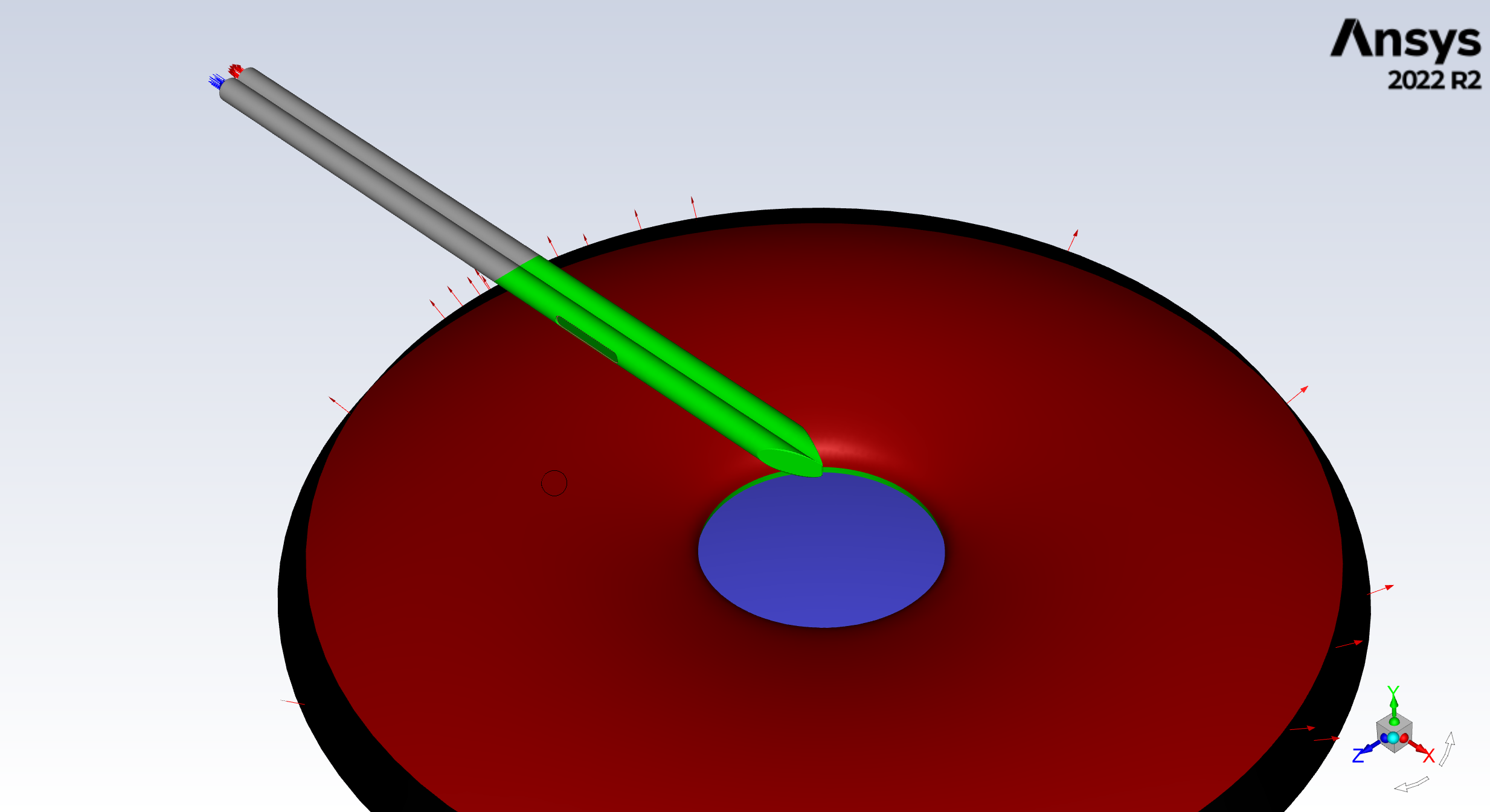
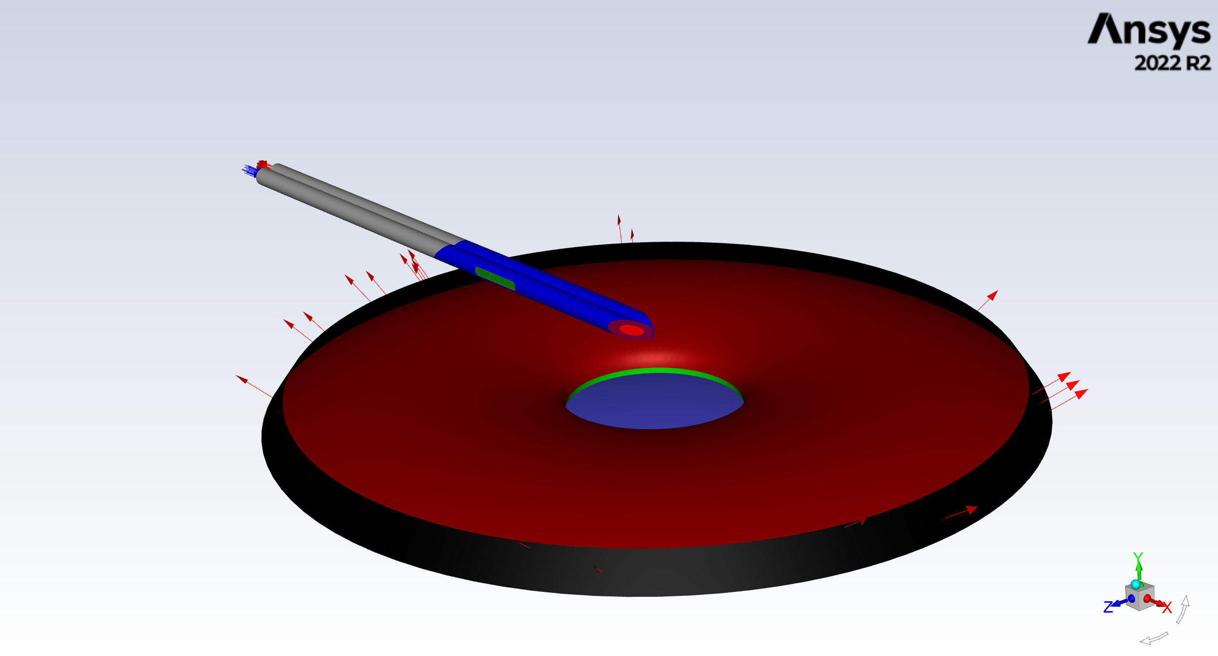
the first picture shows the new geometry with two internal oenings (one on each needle) and the other picture the old geometry with four internal openings. the dimensions of the two models are the same.
-
April 23, 2024 at 3:32 pm
Rob
Forum ModeratorNon conformal is the term used when you have disconnected mesh that's then connected in Fluent using an interface. As you're using internal/interior that's not the case. Assuming the various holes are labelled internal surfaces you can switch to wall in Fluent's boundary conditions which ought to avoid the need to go back to meshing.
If you are removing any surfaces you may need to check what reports are linked to the old faces. If you delete those (look in Report Definitions for "invalid") the solver should run.
-
April 24, 2024 at 9:52 am
Oscar Barthel
SubscriberYes, labeling the holes as walls would be an option, but only for this specific change of geometry. I want to find a general solution that will also work for eg changing the size and position of the holes or increasing the diameter of the tubes.
I tried to delete the report definitions but when i initialized the case i got the following errors:
Hybrid initialization is done.
==============================================================================
Node 2: Process 19828: Received signal SIGSEGV.
==============================================================================
==============================================================================
Node 6: Process 19756: Received signal SIGSEGV.
==============================================================================
==============================================================================
Node 7: Process 916: Received signal SIGSEGV.
==============================================================================
==============================================================================
Node 0: Process 4060: Received signal SIGSEGV.
==============================================================================
999999: mpt_accept: error: accept failed: No such file or directory
999999: mpt_accept: error: accept failed: No such file or directory
999999: mpt_accept: error: accept failed: No such file or directory
...
999999: mpt_accept: error: accept failed: No such file or directory
999999: mpt_accept: error: accept failed: No such file or directory
===================================================================================
= BAD TERMINATION OF ONE OF YOUR APPLICATION PROCESSES
= RANK 1 PID 21516 RUNNING AT FING-10413
= EXIT STATUS: -1 (ffffffff)
===================================================================================
===================================================================================
= BAD TERMINATION OF ONE OF YOUR APPLICATION PROCESSES
= RANK 3 PID 16056 RUNNING AT FING-10413
= EXIT STATUS: -1 (ffffffff)
===================================================================================
===================================================================================
= BAD TERMINATION OF ONE OF YOUR APPLICATION PROCESSES
= RANK 5 PID 21604 RUNNING AT FING-10413
= EXIT STATUS: -1 (ffffffff)
===================================================================================
The fl process could not be started.
Is there an alternative way to change the geometry and therefore the mesh in an existing case? Maybe i can somehow export my case settings like report definitions, created surfaces and solution animations and load them into a new case with the changed geometry
?
-
April 24, 2024 at 12:35 pm
Rob
Forum ModeratorIf you're monitoring on the holes then gaining or losing surfaces may cause problems with the reports. Otherwise the solver should read in a new mesh without too many issues. Look in the /file TUI menu for settings file options.
-
April 25, 2024 at 2:31 pm
Oscar Barthel
Subscriberi tried to read in the new mesh and deleted every report definition beforehand but i still got the same errors:
pop up window:
zone-surface: invalid thread[2]
console:
Error at host: zone-surface: invalid thread[2]
Error at Node 0: zone-surface: invalid thread[2]
Error: zone-surface: invalid thread[2]
Error Object: #f
i also tried to only read in a settings file in the new case but this still led to the same errors. I even tried to use a different new geometry which had the same amount of internal openings as the old geometry from which i extracted the settings file but it still didnt work and produces the same error as before. Do you have any idea what could solve this error?
By the way thank you very much for your time, i really appreciate it :)
-
April 25, 2024 at 3:18 pm
Rob
Forum ModeratorIs the mesh fully conformal? Ie no contact or interface zones.
-
May 2, 2024 at 8:22 am
-
May 2, 2024 at 10:40 am
Rob
Forum ModeratorI can only see one volume in the above.
-
May 6, 2024 at 2:08 pm
Oscar Barthel
Subscriberyes, "Nadeln". Is that a problem?
-
May 7, 2024 at 9:24 am
Rob
Forum ModeratorWhat connects the two parts? In the CFD model you have 3 fluids, but in geometry only one?
-
- The topic ‘Changing the geometry in existing case’ is closed to new replies.


-
3432
-
1057
-
1051
-
896
-
892

© 2025 Copyright ANSYS, Inc. All rights reserved.


