-
-
January 11, 2025 at 7:42 amZwernjaydenSubscriber
My chamber was designed to achieve a chamber pressure of 313.7 psia, and exit pressure of 13.7 psia. I have calculated the required mdot using 2000lbf thrust, C*, thrust coefficient from NASA CEA. My goal is to simulate gaseous ethanol and lox combustion to verify the chemical kinetics before switching to DPM, and model a liquid injection. I set arbitrary inlet areas so that the ethyl alcohol vapor and oxygen have similar velocities. I did not model the exact areas as my actual case will be liquid with much higher densities. I am using a non-premixed steady diffusion flamelet model and mass flow inlet BC. That being said, I am getting a chamber pressure far below what I should be getting despite the combustion working. I am a bit confused why, as the chamber pressure should be set by the throat area and mdot. Is this likely an issue with my rough inlet modelling choices, the fact that gasous combustion has a higher C* than liquids, inconsistencies with the specific heat capacity ratio, or something else? I am also unsure how total pressure in the inlet streams can be close to zero when the static and total pressure at the inlet is 120 psi.
-
January 13, 2025 at 11:25 amRobForum Moderator
You may want to extend the domain to avoid adding mass straight into the nozzle. However, the streaking in the results isn't good. I'm assuming you've accounted for the domain being 2d as opposed to 2d axi-symmetric? Also, plot the contours with no mesh surface selected in 2d, it'll improve the the image quality.Â
-
January 14, 2025 at 7:07 pmZwernjaydenSubscriber
Â
Â
Â
Â
When you say extend the domain, do you mean downstream of the nozzle? Extending and seperating the inlets upstream didnt seem to help, actually made it worse. Also it is 2d axi-symmetric sorry if that wasnt clear. I just have both sides displayed. By streaking do you mean the seperation between the streams like you can see below? Im not really sure why its happening. Could be the mechanism I am using was made for lower pressures, but I get similar results when I use the chemical equilibirum option instead of a flamelet
Â
Â
-
-
January 15, 2025 at 9:43 amRobForum Moderator
Thanks for clarifying the 2d-axi - it's an easy error to make.Â
The streaking must be caused by something. What other models are you using?
-
January 15, 2025 at 6:28 pmZwernjaydenSubscriber
Â
Its a pretty simple combustion case. Non-premixed, diffusion flamelet using LLNL Chemkin mechanism (although I get the same streaks when I use eddy dissipation). KW-sst turbulence model, mass flow inlet for c2h5oh and o2, pressure outlet. Standard initialization at the expected chamber pressure. When I run a transient case I don't get the same streaks for some reason.
Â
-
-
January 16, 2025 at 3:32 pmRobForum Moderator
That sounds like a convergence issue. How do the residuals, monitors and flux balances look?
-
January 16, 2025 at 5:22 pmZwernjaydenSubscriber
It converged really well (~1e-3 or lower) and all fluxes stabalized
-
-
January 16, 2025 at 7:24 pmjcooperAnsys Employee
Hi:Â
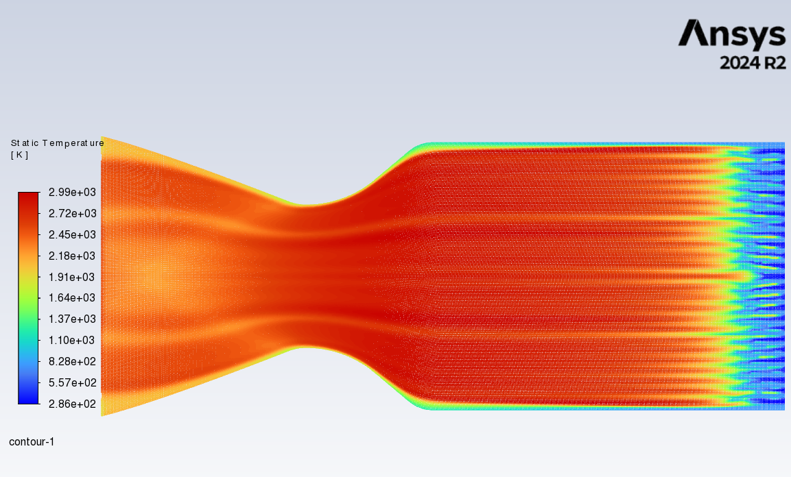
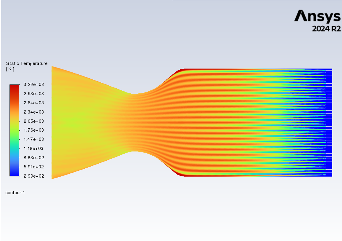
I agree that the solution domain should be extended, especially at the inlet, so that the flow can develop before it hits the throat. Can you please post your velocity and density contours?Â
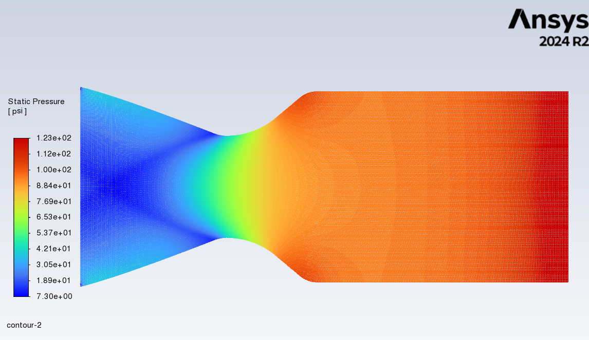
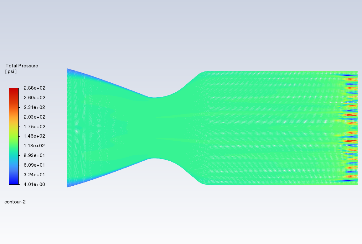
If the solution converged well and didn't give the expected pressure, it is most likely the boundary conditions that are wrong, or the solution has fallen apart and converged to the wrong answer.
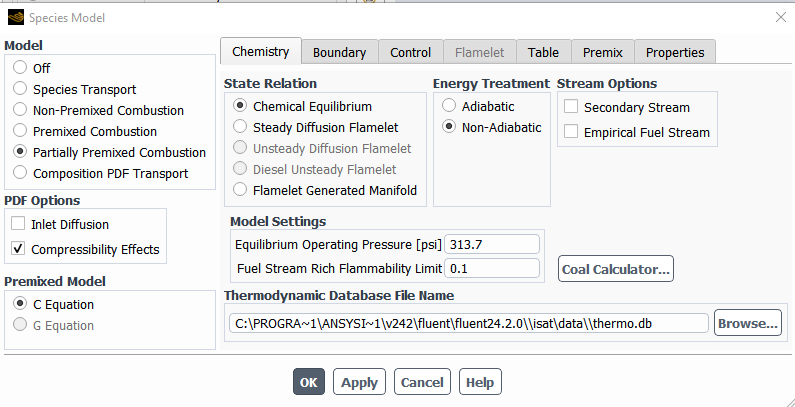
As far as being able to predict the chamber pressure with an empirical equation: I am not sure how well this will work. The thrust equation cannot fully account for what happens during combustion. From the geometry, it looks like fuel and oxidizer are entering together at the inlet. The partially premixed model with chemical equilibrium or a premixed flamelet (if combustion is not equilibrium), is more appropriate. Compressibility effects should be activated for the PDF calculations to account for the big pressure change.
Something like this, or you can use Flamelet Generated Manifold for full chemistry:
Â
Start the calculation with mixture fraction and progress initialized to zero and get the cold solution.
Then, patch progress downstream of the throat and get the combustion solution.
-
January 16, 2025 at 7:41 pmZwernjaydenSubscriber
The streams are not mixed, the inlets are just directly next to each other so I used non-premixed. This was just an assumption and obviously not possible. If I extend the inlets and add space between them I get a similar result though. Chamber pressure is a design parameter you design your engine around. You choose the chamber pressure, then use something like CEA to get your C*, then you can determine what mdot and throat area you need to maintain that chamber pressure for a given thrust. This means that if your C* is lower than expected, your chamber pressure will be lower then expected, but it would have been impossible for it to be as low as I am seeing.
-
-
January 16, 2025 at 8:56 pmjcooperAnsys Employee
Hi:
If the fuel will be atomized into tiny droplets and evaporate rapidly, a premixed inlet may be closer to reality.
Can you please superimpose your mesh lines on one of the striped solutions with the Draw Mesh option? I'd like to see if there is a correlation. A plot of Absolute pressure would also be helpful.
Is the nozzle choked? This would explain the disconnect at the outlet, and also the artefacts in the solution.
It also looks like there is no density change with pressure, except at the outlet, but hard to tell from the scale.
Please check for choke and try regenerating the PDF as an FGM with compressibility effects on. The partially premixed model is also valid for non-premixed combustion and often more accurate than non-premixed model
-
January 16, 2025 at 9:12 pmZwernjaydenSubscriber
The screenshots in the original post have mesh lines on, is that what you mean? The nozzle is choked, the disconnect at the outlet is due to the chamber pressure not being at the value it was design for, so the Po/P ratio is incorrect. This also causes the exit velocity to be too low. There is a density change with pressure, like what you would expect with isentropic flow, its just not visible at the scale as the density of the inlet is so high. My ambient pressure is 14.7 psi so absolute pressure will just be the static pressure image I posted plus 14.7 psi
-
-
January 16, 2025 at 9:42 pmjcooperAnsys Employee
Yes - sorry - the mesh is really fine, so I didn't see the lines.
I still think this is a boundary condition issue and that there is something wrong with the solution because the boundary conditions that are set cannot be achieved. What does a plot of Mach number look like?
Judy
-
January 16, 2025 at 10:16 pmZwernjaydenSubscriber
Yes I understand that its not physically possible, but I didnt see another way of validating the combustion mechanism without involving multiphase for lox and ethanol which would be my next step. I just had to set the mass flow rate that I knew would be true, and try a range of temps that would make it either a gas or a liquid. I got similar results for the range of temps that I tested, and similar results both in chamber pressure and the weird streaks when using eddy dissipation instead of non-premixed which is why I was confused.
Â
-
-
January 16, 2025 at 11:29 pmjcooperAnsys Employee
This nozzle is fully choked, which means that the outlet has stopped communicating with the inlet. Such a flow can still converge, but the solution will be unphysical. Because of the need to match temperature, pressure and velocity of the flow, only the real state will work, unfortunately
You could try solving the nozzle with CFX, which has a homogeneous binary mixture treatment for multiple phases that avoids having to model two phases  This allows you to enter each specie as a mixture of the liquid and vapour, rather than only the gas state; this may bring you closer.
-
January 17, 2025 at 3:18 amZwernjaydenSubscriber
Are you saying that fluent can't solve any choked flow/supersonic nozzle problems, or it just cant solve my case because its non-physical. Not sure what you mean by "only the real state will work"
-
-
- You must be logged in to reply to this topic.
- How do I get my hands on Ansys Rocky DEM
- Non-Intersected faces found for matching interface periodic-walls
- Unburnt Hydrocarbons contour in ANSYS FORTE for sector mesh
- Fluent fails with Intel MPI protocol on 2 nodes
- Help: About the expression of turbulent viscosity in Realizable k-e model
- Cyclone (Stairmand) simulation using RSM
- Mass Conservation Issue in Methane Pyrolysis Shock Tube Simulation
- Script Error
- Facing trouble regarding setting up boundary conditions for SOEC Modeling
- convergence issue for transonic flow
-
1436
-
599
-
591
-
591
-
366
© 2025 Copyright ANSYS, Inc. All rights reserved.