TAGGED: gravity
-
-
November 15, 2024 at 4:36 am
s113010505s
SubscriberRecently, I attempted to simulate breast deformation from the prone to supine position, but I encountered some challenges. I'd appreciate any advice that might help.
The model, segmented from MRI images, uses a Mooney-Rivlin hyperelastic material model with parameters shown below.
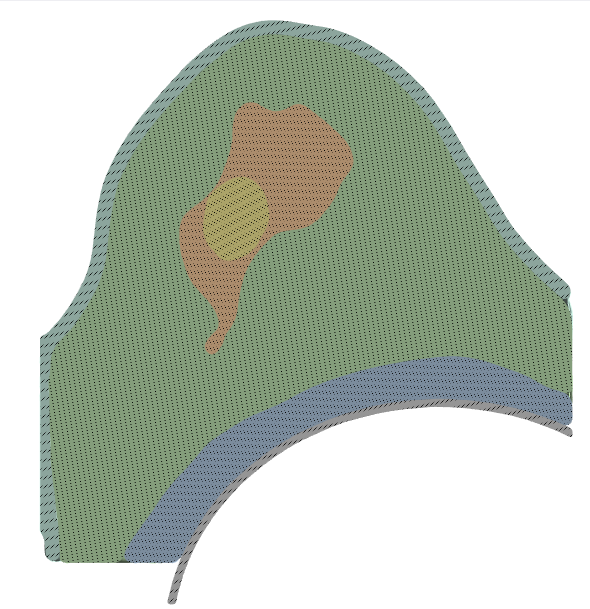
*outside: skin, green: fat, orange; fibroglandular tissue, yellow: tumor, blue: pectoral muscle, gray: chest wall
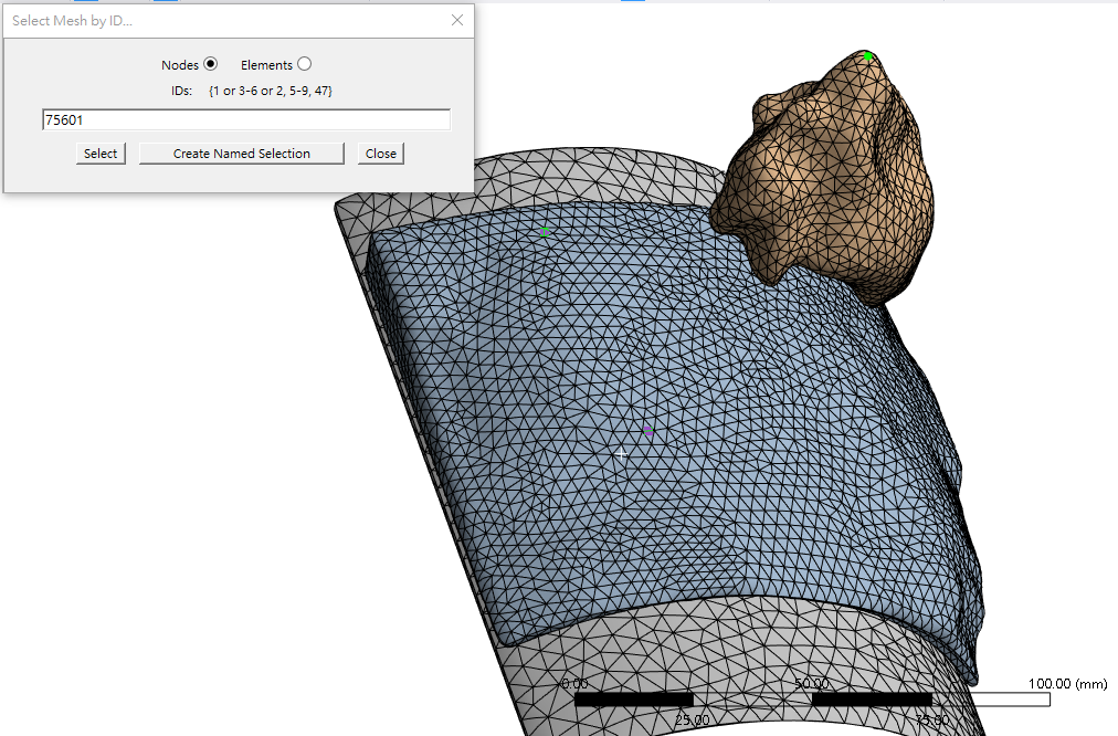
The mesh is tetrahedral, with a 3 mm element size. For contacts, I used the default settings in Workbench, except for a frictionless sliding contact between the pectoral muscle and chest wall; other contacts are set to "no separation."
The boundary conditions are based on configurations from several studies:
- All faces of the chest wall are fixed.
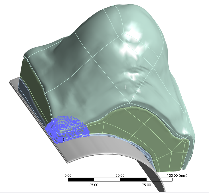
- The edge near the sternum is fixed.
- Select nodes around the corners are fixed to prevent rigid displacement.

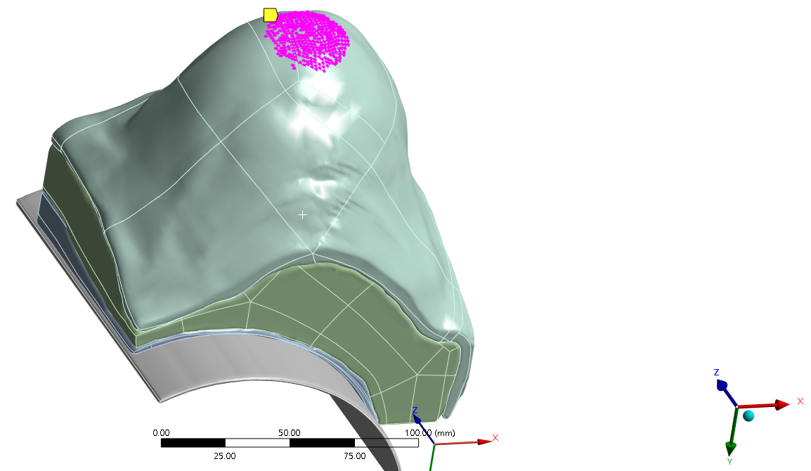
- Nodes at the anterior end are constrained to deform only in the X and Y directions.

To simulate the prone-to-supine deformation, I applied twice the gravity on the model, enabling “large deflection” for the large expected displacement. The initial substeps were set to 100, with a minimum of 10 and a maximum of 1000.
After these settings, the solution failed, producing error messages related to node 75601. I’ve tried several adjustments—reducing the mesh size to 1 mm, increasing “number of steps” to 20, and enabling "nonlinear adaptive region" for all bodies in the model—but these attempts did not resolve the errors.
I want to know the reasons for these persistent errors and want to get some suggestions to improve the simulation. I’d be very grateful for any advice. Thank you!
-
November 20, 2024 at 1:56 pm
John Doyle
Ansys EmployeeThe error messages are general indications of an underconstrainted model. My guess is that the contact between the components is insufficient. You might have done this already, but if not, I would insert a Contact Tool under the Connections branch. Then generate initial conditions for all the pairs to understand how the code is interpreting the initial status of these pairs. Is the pinball radius sufficient to establish an initially closed condition? Is the scoping sufficient to capture all the critical surfaces? What is the code calculating for initital gaps and penetrations? I recommend turning off Trim (in contact pair details window), to make certain that we are not removing contact elements that need to stay. Perhaps for bonded and no separation, use MPC formulation. Use many substeps. My two cents.
-
- You must be logged in to reply to this topic.


-
3467
-
1057
-
1051
-
929
-
896

© 2025 Copyright ANSYS, Inc. All rights reserved.


