Ansys Assistant will be unavailable on the Learning Forum starting January 30. An upgraded version is coming soon. We apologize for any inconvenience and appreciate your patience. Stay tuned for updates.
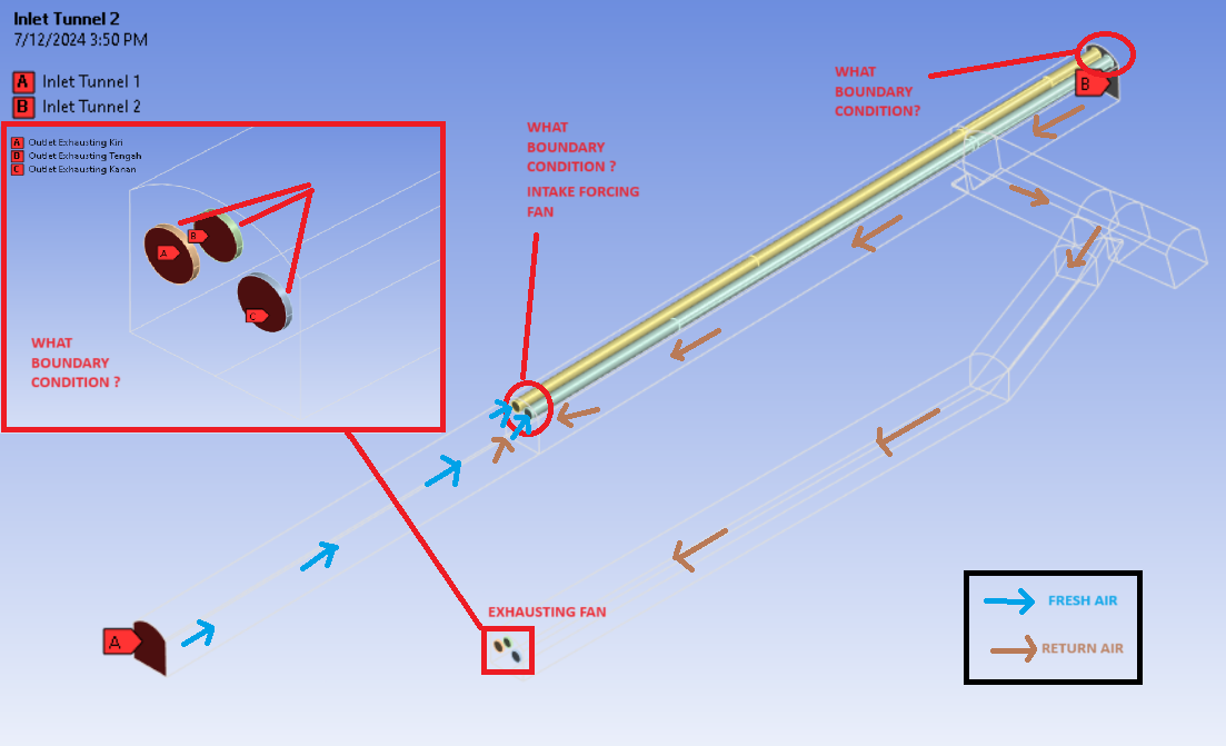
Hi all, i want to perform an analysis of air recirculation and determine the percentage of dirty air that enters the intake duct (forcing fan system, 2 ducts). I am having difficulty defining the boundary condition for the intake forcing duct so that it can draw air from velocity inlet tunnel 1 and 2 as shown in the picture.
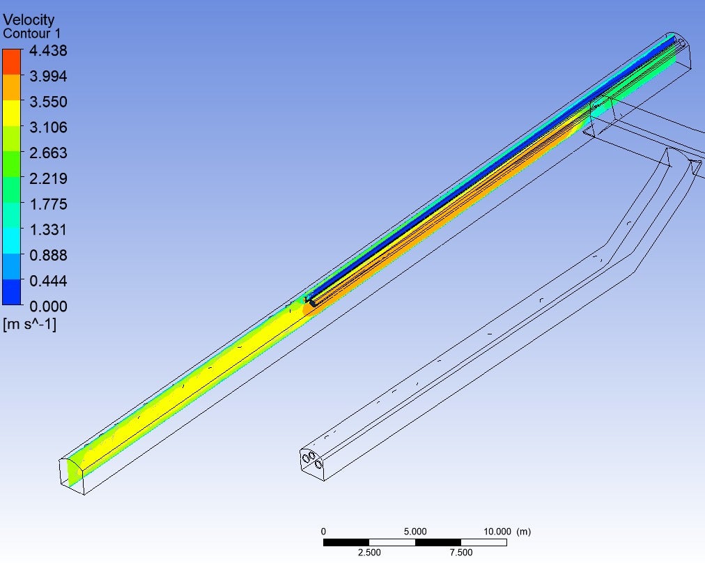
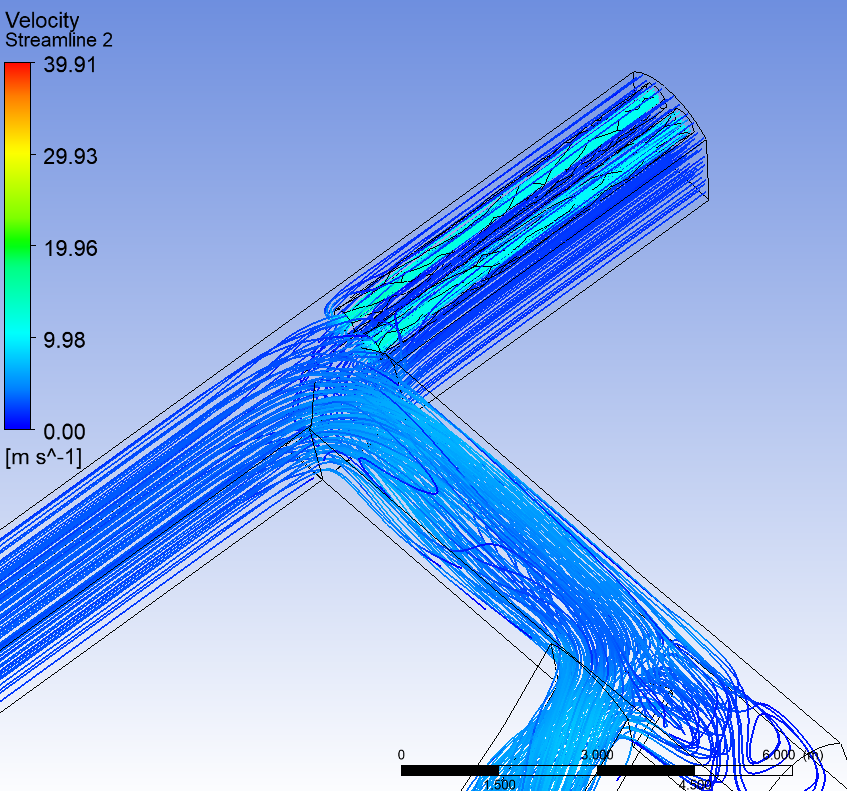
For the time being, I have tried to define the front part of the duct as the "fan" boundary condition and set a constant speed of 19.6 m/s. However, when generating the report, why does the duct not showing any air velocity? As can be seen in velocity contour 1 (blue contour).
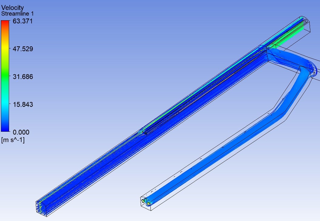
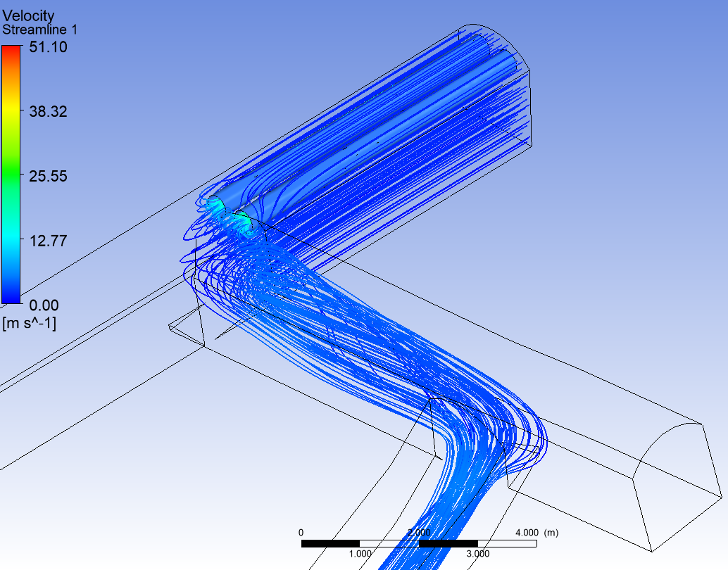
Also in the streamline report, it can be seen that the forcing duct is not drawing any air at all.
What is the problem? can someone help me step by step to fix it?
Thank you,
July 15, 2024 at 12:22 pm
Rob
Forum Moderator
Go through all of the boundary settings but also look for wall, and wall & shadow pairs. A lack of flow "somewhere" can be real (there's nothing driving flow), poor choice of boundary conditions (you've got a wall where you didn't expect it) or a post processing hiccup (releasing pathlines from a surface will show where that fluid goes, not that anything is entrained by that boundary).
July 17, 2024 at 8:25 am
Zen
Subscriber
Thank you Rob, i just resolved my problem. Then, how do i know the percentage of air recirculation (percentage of air that flowing through the duct and not flowing through the duct based on this CFD post-processing.
July 17, 2024 at 9:11 am
Rob
Forum Moderator
Have a look at the boundary flux reports. Assuming each boundary is unique then you can find the mass in/out.
July 17, 2024 at 3:39 pm
Zen
Subscriber
Got it, but how can I calculate the mass flow rate of air produced only by the tunnel located at the top right? If I use a flux report, the value will surely include the mass flow rate from both the tunnel at the top right and the tunnel at the bottom left. Please advise on what I should do. Thank you.
July 19, 2024 at 10:20 am
Rob
Forum Moderator
Flux reports are on a per surface basis so provided you labelled the outlet faces etc you're good to use the Expressions.
July 19, 2024 at 2:35 pm
Zen
Subscriber
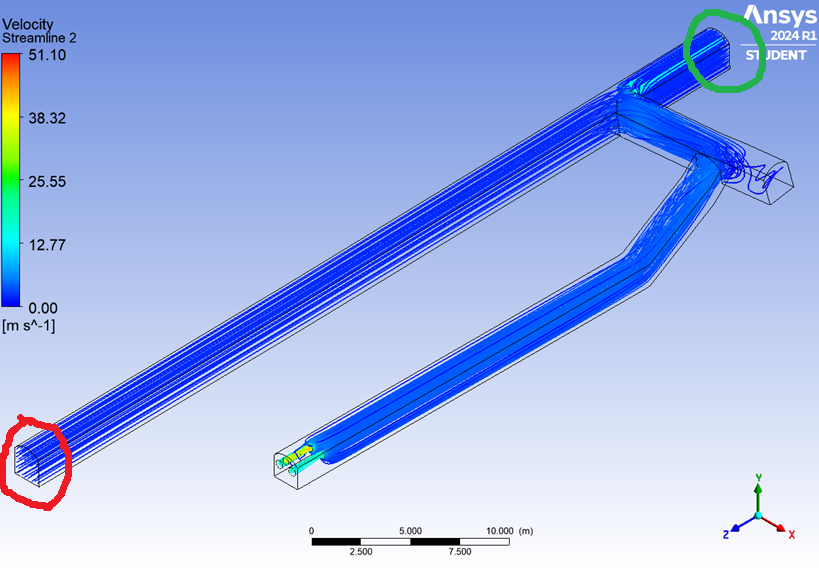
I apologize for any confusion caused by my previous question. Yes, I can perform a flux report by selecting the face in front of the duct that will be traversed by a mass flow rate. When I perform a flux report, the resulting value will surely represents the total mass flow rate passing through the selected area/face, meaning it will be influenced by the mass flow rates from inlet 1 (red) and inlet 2 (green).
Is there a way to determine the mass flow rate from the flux report that is influenced only by inlet 2 (green)? I specifically want to know the value of the return air (inlet 2) that re-enters my intake duct while ignoring the mass flow rate from inlet 1. Thank you.
July 22, 2024 at 9:43 am
Rob
Forum Moderator
Ah, yes, it's for both surfaces. In CFD Post you can probably use a plane near the boundary. In Fluent I'd just separate the boundary to get boundary and boundary:014 (example names) and report there. Other than some very specialised options I'd not use CFD Post with Fluent data.
Viewing 5 reply threads
The topic ‘Boundary Condition Definition’ is closed to new replies.
The Ansys Learning Forum is a public forum. You are prohibited from providing (i) information that is confidential to You, your employer, or any third party, (ii) Personal Data or individually identifiable health information, (iii) any information that is U.S. Government Classified, Controlled Unclassified Information, International Traffic in Arms Regulators (ITAR) or Export Administration Regulators (EAR) controlled or otherwise have been determined by the United States Government or by a foreign government to require protection against unauthorized disclosure for reasons of national security, or (iv) topics or information restricted by the People's Republic of China data protection and privacy laws.
Please Login to Report Topic
Please Login to Share Feed
Edit Discussion
You are navigating away from the AIS Discovery experience
The Ansys Learning Forum is a public forum. You are prohibited from providing (i) information that is confidential to You, your employer, or any third party, (ii) Personal Data or individually identifiable health information, (iii) any information that is U.S. Government Classified, Controlled Unclassified Information, International Traffic in Arms Regulators (ITAR) or Export Administration Regulators (EAR) controlled or otherwise have been determined by the United States Government or by a foreign government to require protection against unauthorized disclosure for reasons of national security, or (iv) topics or information restricted by the People's Republic of China data protection and privacy laws.