-
-
June 16, 2018 at 9:37 am
Fabricio.Urquhart
Subscriber[Edit: continuation of this post]
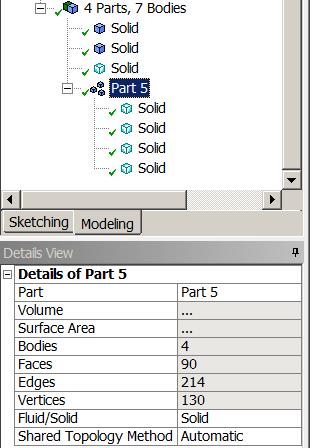
Yes, it happened as I was expecting. I did not use slice, but form the part, and use base face split with mesh control.
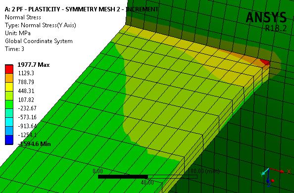
The results are the same, I have a peak of stress, and I do not know why. In the Eurocode this connection has Mrd = 100kNm.
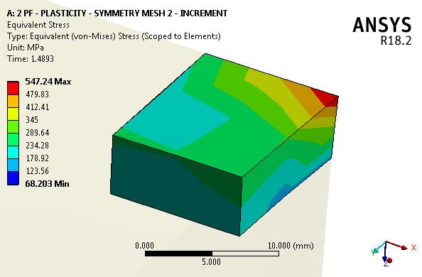
With the model Mrd is under 30kNm. There is something wrong in the model. I think that it is impossible to be the weld. As you see, the results are completely different from your model. Really, I don't know where is the problem with the model. If I take the element results, ts the picture below:
If I take probe, in the node of the element before, the results are in the picture below. As you, see, completely different, nearer of the reality, but not reliable.
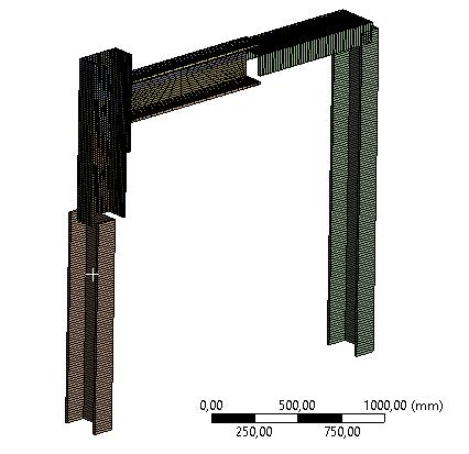
Just a moment, I will attach the model which is solved.
-
June 16, 2018 at 11:40 am
peteroznewman
SubscriberThere is something wrong with your model.
Add a Directional Deformation for the weldment part in the Y axis and zoom in to the connection between the beam and the plate. The deformations should be continuous across the corner. Instead there is a 0.7875 mm gap opened up under this load.
Your beam mesh is only connected at 4 nodes, not along the entire edge.
I created a 2-element thick model, and when I do the same check on that as I describe above, it reveals an unconnected thin strip along the back edge, though there is a good connection of the beam to the plate.
The corrective action is to loosen the node merge tolerance and/or add mesh edge controls so that coincident edges have the same number of nodes along them.
-
June 16, 2018 at 7:06 pm
peteroznewman
SubscriberI changed the Mesh Edit Node Merge group to a 0.5 mm tolerance and said yes to Face to Edge and Edge to Edge. Now 368 nodes were merged.
Here is the new Y directional deformation plot. It appears that there is no longer a "crack" in the mesh.
See this discussion for the question of how to find out about unintended "cracks" before solving.
-
June 18, 2018 at 4:15 pm
Fabricio.Urquhart
SubscriberPeter, it is true, you found this problem. But if you plot normal beam stress versus time. You will see the peak of stress yet.I think that there is anotther problem. I am looking for it.
Did you plot the stress?
Regards!!
-
June 19, 2018 at 2:47 am
peteroznewman
Subscriber -
June 19, 2018 at 11:40 am
-
June 19, 2018 at 11:17 pm
peteroznewman
SubscriberI found a reason why meshing from the earlier DesignModeler geometry was failing to create congruent meshes.
The part shows Shared Topology Method is set to Automatic, which is correct but...
... the individual bodies had the Shared Topology Method set to None, which defeats the Part level setting.
All bodies in the Part must be set to Automatic.
-
June 20, 2018 at 2:15 am
Fabricio.Urquhart
SubscriberPeter, with it, the results are the same. The peak of stress still appear. I divide the mesh around the holes in more than 3 parts. And the results are the same.
I really do not know what to do. The Ansys results are not being reliable, and this peak of stress represents that there is still something wrong.
What do you think about this peak of stress?
-
June 20, 2018 at 2:37 am
Fabricio.Urquhart
SubscriberThis message appear: "The selective body meshing is not being recorded, so the meshing may not be persistent on an update. If you want to record the order of the body meshing, please use the Mesh Worksheet to track the meshing steps. Please see Selective Meshing documentation for more details.".
Maybe this is the reason, is it mean that the mesh is not being used when ansys solves?
Thank you very much Peter!
-
June 20, 2018 at 9:44 am
peteroznewman
SubscriberThe message about "selective body meshing" means that the mesh was built by the user selecting a body and requesting a mesh on that body. This can be useful if Generate Mesh results in a failed mesh. Generate Mesh lets the software choose the order in which to mesh the bodies and it can "paint itself into a corner" where the last body it meshes has conflicting constraints imposed on it from previously meshed adjacent bodies and there is no valid mesh on the last body. The user sees this failure, Clears the mesh, and picks the failed body to mesh first. The user can selectively build the mesh in a preferred order, then at some point can let the software finish the job. This often results in a valid mesh. The message is telling you that if you Clear the mesh, you won't get the same mesh again if you let the software pick the order of meshing. This can be overcome by recording the user selected build order in a Mesh Worksheet. Whatever mesh is built is used.
Please upload your latest archive and I will take a look at the peak stress. Why do you think it is wrong?
-
June 20, 2018 at 1:24 pm
Fabricio.Urquhart
SubscriberI have four points to say the results are wrong:
1- I should model a column in place of the fixed plate
2- If I compare with the Eurcode results - Part 1, it is completely different.
3- This pick of stress in the beam, is only in one element/point
4- Maybe I have to model the weld, to take out a stress concentrate point (face to edge)
The last model is attached.
Thank you Peter! -
June 20, 2018 at 2:40 pm
peteroznewman
SubscriberI don't have a copy of Eurocode - Part 1, so I don't know what you are trying to compare with.
When you have plasticity, concentrated stress can't go above the material stress-strain curve, it just creates plastic strain that redistributes the stress and is the whole point of adding plasticity to your model.
I'm running your model now and will write more when I have the solution.
-
June 20, 2018 at 4:35 pm
Fabricio.Urquhart
SubscriberPeter, I attached the Eurocode, but it is not necessary to verify this in this moment. The ponti is, that the Ansys Model moment resitance (the join moment when element reach the yields stress) is lower than the moment calculated by Eurocode.
-
June 20, 2018 at 5:21 pm
peteroznewman
SubscriberCan you share with me the moment you calculated following the Eurocode? It's rather a long document!
-
June 20, 2018 at 6:26 pm
Fabricio.Urquhart
SubscriberI have done with Mathcad, is attached.
-
June 20, 2018 at 8:27 pm
peteroznewman
SubscriberPEAK STRESS AT ONE POINT
In the image below, the peak stress is at a point. That is expected. A thin member is pulling away from a thick plate and the interior corner is dead sharp. That creates a stress singularity.
If these materials were elastic, as the element size was reduced, the peak stress would increase without limit.
Fortunately, plasticity has been added to the material model, so the stress is limited by the material model.
If we look at just that one element in the corner and look at an earlier time with less load. Here is the picture:
Note that the yield strength for this material is 345 MPa and the yellow boundary is about to reach an integration point on this element. Now let's look at the stress-time history.
The stress went down after this point. How can that be correct?
Look at the plastic strain on that element. After this point, plastic strain begins.
There is nothing wrong with this model. At the next load increment, this element goes plastic, and reduces stress and the surrounding elements that had lower stress at this time and are still elastic, pick up a little more stress to carry the next load increment, while this corner element sheds some load due to the change to plastic behavior.
-
June 20, 2018 at 10:13 pm
peteroznewman
SubscriberEUROCODE MOMENT CALCULATION
There were many MathCAD files in the attachment above. Which file has a calculation that you want to compare with the ANSYS model? -
June 20, 2018 at 11:42 pm
Fabricio.Urquhart
SubscriberPeter, my strain graph is different of yours. Look at my graph:
Your graph is similar to the minimum strain graph. The maximum you have the same peak. I solved the elastic model minutes ago and saw that in this point the beam reach the plasticity.
But I did not understand why our graphs are different.
The name of the file is: "FTRd - Chapa de Extremidade - 2a linha PF"
The files are all types of verification, discondering the column resistance.
-
June 20, 2018 at 11:58 pm
Fabricio.Urquhart
SubscriberPeter!!!Sorry, the verifications are for two lines of bolt in tension. For just one line I did not do, I was comparing two analysis different.
So Sorry!
-
June 21, 2018 at 1:00 am
peteroznewman
SubscriberFabricio,
The plasticity material means you can plot three values of strain: Total, Plastic and Elastic where
Total = Plastic + Elastic
You have plotted Elastic and I plotted Plastic.
Regards,
Peter
-
June 21, 2018 at 1:41 am
Fabricio.Urquhart
SubscriberNow I understood. I think that I will try to model the column in place of the rigid plate now.
Thank you for your help!!!
-
June 22, 2018 at 12:55 am
peteroznewman
SubscriberYou did a great job on the mesh so far, I'm sure you can whip the column into shape.
You also know more about keeping the Shared Topology working now.
-
June 23, 2018 at 10:49 pm
Fabricio.Urquhart
SubscriberThank you Peter!!I I reachef an excelent mesh. Now I am modelling a portic, I am studying how to create join between cross section and solid model.
Best regards!! -
June 24, 2018 at 2:00 pm
Fabricio.Urquhart
Subscriber -
June 24, 2018 at 5:10 pm
peteroznewman
SubscriberI think you have to specify beam section alignment in DesignModeler. You can specify it in Mechanical is it is a geometry operation.
-
June 24, 2018 at 5:44 pm
Fabricio.Urquhart
SubscriberOk. I understood. And the symmetry that I have applied, is it OK for the line bodies?
Another question, is about the load, I will add a load along the beam, and along the beam modelled by solids. So I have two points:
1 - The local buckling that will occure in the beam solid, or with the symmetry, the load is applied along the center line?
2 - Do I have to divide the load for two beacuse the symmetry, yes?
Thank you Peter!!
-
June 24, 2018 at 6:04 pm
peteroznewman
SubscriberLoads applied to a model using symmetry must be cut in half if the symmetry plane is cutting the face the load is applied to is cut in half.
When a beam is perpendicular to a plane of symmetry, that I understand is valid. I am unsure about using a beam that lies in the plane of symmetry. What happens to the cross-sectional area of the beam? Is it automatically handled or do you have to manually alter the beam cross-section for beams that lie in the plane of symmetry? I can't say for certain without some research. You could build a small model to see what happens if you are interested.
If you are interested in local buckling in an I-beam, don't use beam elements. Beam elements have a fixed cross-section that cannot have local buckling of one flange in a local area. If you model an I-beam with shell elements, then the shell elements can buckle out of the plane of the flange.
Regards,
Peter
-
June 24, 2018 at 7:00 pm
Fabricio.Urquhart
SubscriberI have modeled the cross section with the proprietes of the same solid beam, but the half section, because the symmetry plane, so I think if I apply the load in the half load in the beam, and the same load in the top flange of the solid. It will be Ok. The question was, if the local buckling maybe result different stress results.
The objective is to analyse the stifness of the bolted connection. But now the problem, I think that is the bolts stress, because when the load starts to be applied, the bolts reach the yield stress.
-
June 24, 2018 at 9:08 pm
peteroznewman
SubscriberLOCALIZED BUCKLING OF I-BEAMS
You have to decide if you want to include this in the model or not. It requires some serious attention if you do, but I don't think it is central to your study of bolted joint stiffness so I recommend you don't try to include this in your model.
BEAMS THAT LIE IN THE SYMMETRY PLANE
You haven't convinced me that you know the correct way to treat these in the model. I want to see three models: (1) a beam without symmetry and a full cross-section, (2) a beam with symmetry with a full cross-section and (3) a beam with symmetry with a half a cross-section. Show me which symmetry model (2) or (3) matches the results of the model without symmetry (1).
FASTENERS ENTERING PLASTIC DEFORMATION
This is not a problem when taking a bolted joint past its elastic range. Something has to give and the point of the model is to find out what is going to give first. -
June 24, 2018 at 11:33 pm
Fabricio.Urquhart
SubscriberPeter, thank you!
I will not include localized buckling of I-beam.
I will do those models and find the correct way. After that I show it to you. If I haD difficulty with it, I will ask you.
Ok, something has to give. But the bolt is given before the load is applied. The bolt gave with the pre-load tension. Did you understand?
-
June 25, 2018 at 9:56 pm
peteroznewman
SubscriberFabricio,
Some people specify tightening a fastener to its yield point. That is not a problem.
When you report the beams in the plane of symmetry, a simple model is just a beam in tension.
Regards,
Peter -
June 26, 2018 at 12:23 am
Fabricio.Urquhart
SubscriberPeter, but the fasteners are modeled. I think that you would like to say washers, wouldn't you?
-
June 26, 2018 at 12:46 am
peteroznewman
SubscriberFabricio,
This thing that you modeled with the bolt pretension applied, I call that a fastener, you seem to call it a washer.
A fastener can have a head on one end and a nut on the other end (or it goes into a threaded hole on the joint).
A washer is the flat circular piece that goes under the head or the nut to spread the load and reduce the friction.
-
June 26, 2018 at 1:25 am
Fabricio.Urquhart
SubscriberOk. I understood fastener, in portuguese is "fuste". Peter when I work with simmetry and cross section I have this warning:
One or more MPC contact regions or remote boundary conditions may have conflicts with other applied boundary conditions or other contact or symmetry regions. This may reduce solution accuracy. Tip: You may graphically display FE Connections from the Solution Information Object for non-cyclic analysis. Refer to Troubleshooting in the Help System for more details.
I did not understand what you mean when you said: "When you report the beams in the plane of symmetry, a simple model is just a beam in tension"
How can I use symmetry with beam elements without this warning?I think that is not possible, because the joints.
-
June 26, 2018 at 11:56 am
peteroznewman
SubscriberYou can ignore the warning for this demo model. It says "may have conflicts". Symmetry will put constraints on the nodes, then you will add a fixed constraint to one of those nodes and it is warning you about that. But there is no conflict. They each constrain a DOF in the same way, to be zero.
-
June 26, 2018 at 7:37 pm
Fabricio.Urquhart
SubscriberIf you prefer, we can change this comparation to another topic, involving symmetry with solids and cross section...
-
June 26, 2018 at 8:19 pm
-
June 27, 2018 at 1:50 am
Fabricio.Urquhart
SubscriberPeter, I am studying the problem that is hapenning with de bolts. Do you have any article or post that talk about modelling bolts in Ansys?
Because I think, that applying pretension and using plasticity it will be ok.
Thank you!
-
June 28, 2018 at 1:50 am
-
June 28, 2018 at 9:58 pm
-
July 8, 2018 at 9:39 pm
Fabricio.Urquhart
SubscriberHello Peter, now the model is OK.
The difficulty is how to determinate the moment that the solid beam transfer to the solid column, to plot Moment X Rotation. The rotation I take from the directional deformation in the center of the beam and column, dividing for the length.
But the moment I am trying a way to determinate, do you have any article or reference in Ansys that tell about it?
Thank you, very much!!
-
July 8, 2018 at 10:16 pm
Sandeep Medikonda
Ansys EmployeeHi Fabricio,
I am not caught up on this thread. But based on your question, please check if this article helps? you might need to manually insert some commands.
Regards,
Sandeep
-
July 9, 2018 at 1:37 am
Fabricio.Urquhart
SubscriberThank you Sandeep, I will study some commands. This topic started in moment-x-rotation-steel-bolted-connection.
-
July 9, 2018 at 2:08 am
peteroznewman
Subscriber@Sandeep, the zip file attachment on this post has a paper with the definitions for Moment and Rotation.
Hello Fabricio,
From the paper, M = PL is equation (4), which is for a point load P at a distance L from the column.
You have used a distributed load, q = 40 kN/m for a length, L = 0.872 for the symmetric half model.
You calculate the beam shear and moment diagrams for your problem. I used an online calculator.
So when q = 40 kN/m, M = 15.21 kNm
Regards,
Peter
-
July 9, 2018 at 11:53 am
Fabricio.Urquhart
SubscriberPeter,
In the model, the connection is not rigid neither flexible, so the beam pass some value of moment to the column. A beam with flexible connection in both extreme, the moment will be zero in the extremes, and maximum in the middle, with the value M = (q*L^)/8.
Maybe I have to consider rigid connection and compare this moment, baecause the article compare a cantilever beam and compare the full moment. I am thinking: when this moment is not transfered to the column, the beam rotate.
@Sandeep, in the article we have reactions with cross section models.
It says: "For a Moment Reaction scoped to a contact region, the location of the summation point may not be exactly on the contact region itself."
In my case, it is exactly what is happening. I would like to know the moment transfered between the contact region: bolts and endplate, endplate and column, and bolts and column.
-
July 9, 2018 at 3:42 pm
peteroznewman
SubscriberFabricio, I updated by earlier post with the bending moment diagram for a cantilever beam. The answer for the maximum moment supported is the same regardless of whether you do the pinned end beam where L=1.744 m or the cantilever at L=0.872 m. The pinned beam has a deformed shape more like your model, while the cantilever beam shows the maximum moment at the joint.
-
August 10, 2018 at 12:33 am
Fabricio.Urquhart
SubscriberHello.
I would like your opinion about de moment reaction using symmetry.
When I compare the moment in the connection ( Moment reaction plus Horizontal Y Force Reaction multiplied for 2m, that is the column height) with the rotation (beam rotation minus column rotation, extremely near of the connection), have I to multiply for two, becasue the symmetry?I think that it is not necessary if I am comparing with the full solid, is it?
-
August 10, 2018 at 5:47 pm
peteroznewman
SubscriberYou should have cut the load in half when you cut away half the model. Did you do that? In any case, the load you applied is used to compute the moment and plot that against the rotation.
If the problem specification says to analyze a beam that supports 40 kN/m and you choose to cut the model in half and apply 20 kN/m, you will get the same rotation as if you had not cut the model in half and applied 40 kN/m.
What matters is how you label your Moment axis in the graph, you could label it: Half moment on half model. Then you would show the 20 kN/m moment.
Or you could label it Moment and you would double the 20 kN/m and show the moment for 40 kN/m even though you used 20 kN/m in the half model.
The point is to be clear what you are plotting.
-
August 18, 2018 at 7:00 pm
Fabricio.Urquhart
SubscriberI moved to this discussion Follow-bolted-joint-comparison-to-eurocode-2
-
- The topic ‘Bolted joint comparison to Eurocode’ is closed to new replies.
-
6465
-
1906
-
1458
-
1308
-
1022
© 2026 Copyright ANSYS, Inc. All rights reserved.


