-
-
June 8, 2023 at 11:11 am
Peter
SubscriberAccording to the SpaceClaim Online Help the orientation of a beam is defined as follows:
Orientation: The angle of the profile relative to the path.
If I only have the beam orientation in the global coordinate system (as a vector) how can I calculate the angle relative to the path? How is the local coordinate system of the path defined? -
June 9, 2023 at 10:57 am
Aniket Chavan
Forum ModeratorHi Peter, it seems that you were trying to upload an image, can you please reupload it?
-Aniket
-
June 9, 2023 at 11:06 am
-
June 9, 2023 at 11:31 am
Peter
Subscribersome more clarification:
I have the trace of a beam (given by number of points) and the orientation of the beam in a global coordinate system provided by an external program.
Profile POLYLINE normal 300X8/100X15 [(94.4, 12.324872277, 40.4), (94.4, 12.324872277, 41.3), (94.4, 12.846206209, 42.985)] [1.0, 0.0, 0.0] out of the points i have created the courves and than i put the beams on them.... something like this
for pp in points:
p=pp.split(",")
points3D.append(Point.Create(float(p[0]) , float(p[1]), float(p[2] ) ))
try:
c_beam=GetRootPart().GetComponents(beam_name)[0]
result = SketchNurbs.CreateFrom3DPoints(False, points3D)
curve1=result.GetCreated[IDocObject]()[0]
result = Beam.Create(Selection.Create(curve1), Part2 )
it kind of a works but i am having hard time understandig in what coordinate system the orientation of the beam is defined.....i.e how to calculate the angle relative to the path by only having the orientation of the beam in a global coordinate systemfor example all the beams on the picture below have the same Orientation, but some of them are flipped to the oposite side
-
June 10, 2023 at 8:30 am
mjmiddle
Ansys EmployeeYour code seems to be mssing a bit on how you create the cross section and assign to the beam.
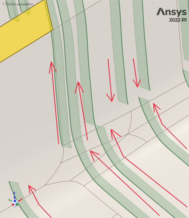
Beams cross sections in the 3D model are oriented (angle) and positioned (distance from centroid) based on the the position of the coordinate system relative to the centroid in the cross section model.It’s using a coordinate system along the beam in the 3D model, so the direction, or rather, starting point of this cross section sweep in the curve in the 3D model matters.
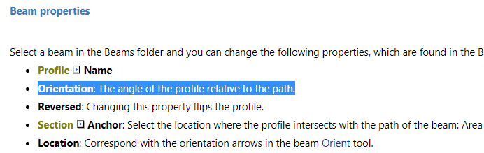
To reorient beam cross sections, you can use the “Prepare > Orient” in the “Beams” section of the ribbon, or use the Move tool to move the cross section solid in the cross section model, or specify a centroid position and orientation angle in the beam properties.
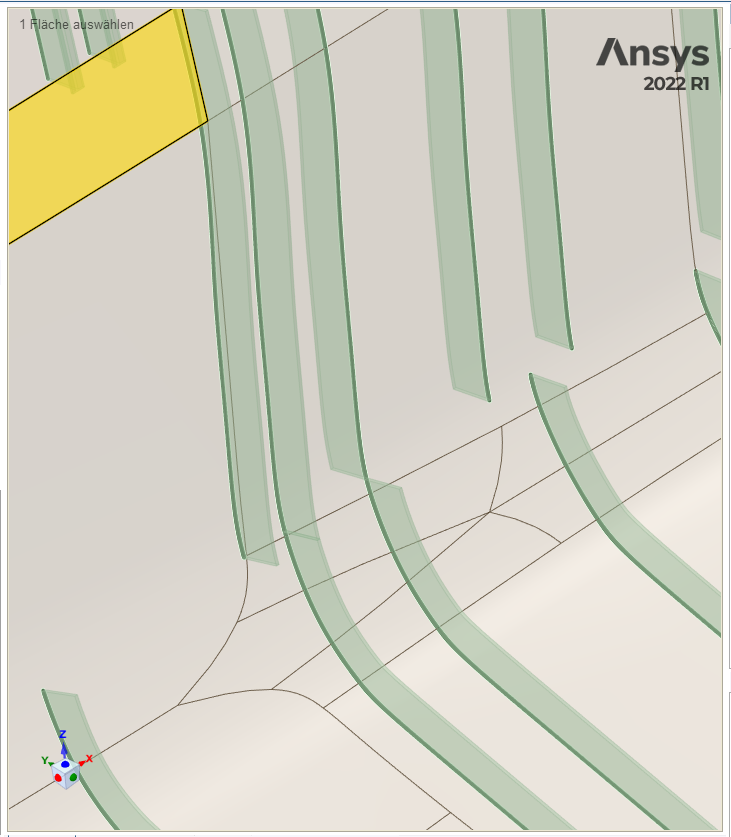
You may have to toggle the “reversed” property in the beam properties or reverse the direction your beams are created. In terms of your script the SketchNurbs curve’s direction will be determined by the order of the points in your list. You must have points ordered as shown below:You’ll have to figure out a way to determine the spatial ordering of the points in your curves to have them all the same general direction. For example, all having lower x to higher x values. Or detect those curves that are the opposite way, and set the “reversed” property. Setting 180 degree orientation should do it too, because you have symmetric shaped cross section (not something like an L shape).
-
- The topic ‘Beam Orientation in SpaceClaim.’ is closed to new replies.
-
5879
-
1906
-
1420
-
1306
-
1021
© 2026 Copyright ANSYS, Inc. All rights reserved.


