TAGGED: 2D, buoyancy, fluent, outlet-boundary-condition, pressure-outlet
-
-
February 16, 2024 at 4:01 pm
Daniel Thomas
SubscriberI have been unable to see the effects of buoyancy on a flame simulation, although the case is chosen as one for which buoyancy should be significant (Fr ≈ 0.3, where the Froude number is the ratio of inertial to gravitational forces). The flow and flame results are approximately what I expect from 1D simulations, but there is no change to the vertical flame position with gravity on or off. I get a slightly different flame position with the outflow and pressure outlet boundary conditions, but no change with gravity for either one. I've also been able to show buoyancy effects within a domain with only horizontal outlets, but this vertical (parallel to gravity) outlet seems problematic.
I'm new to Fluent, and would be grateful for any suggestions on possible problems with boundary conditions or elsewhere.
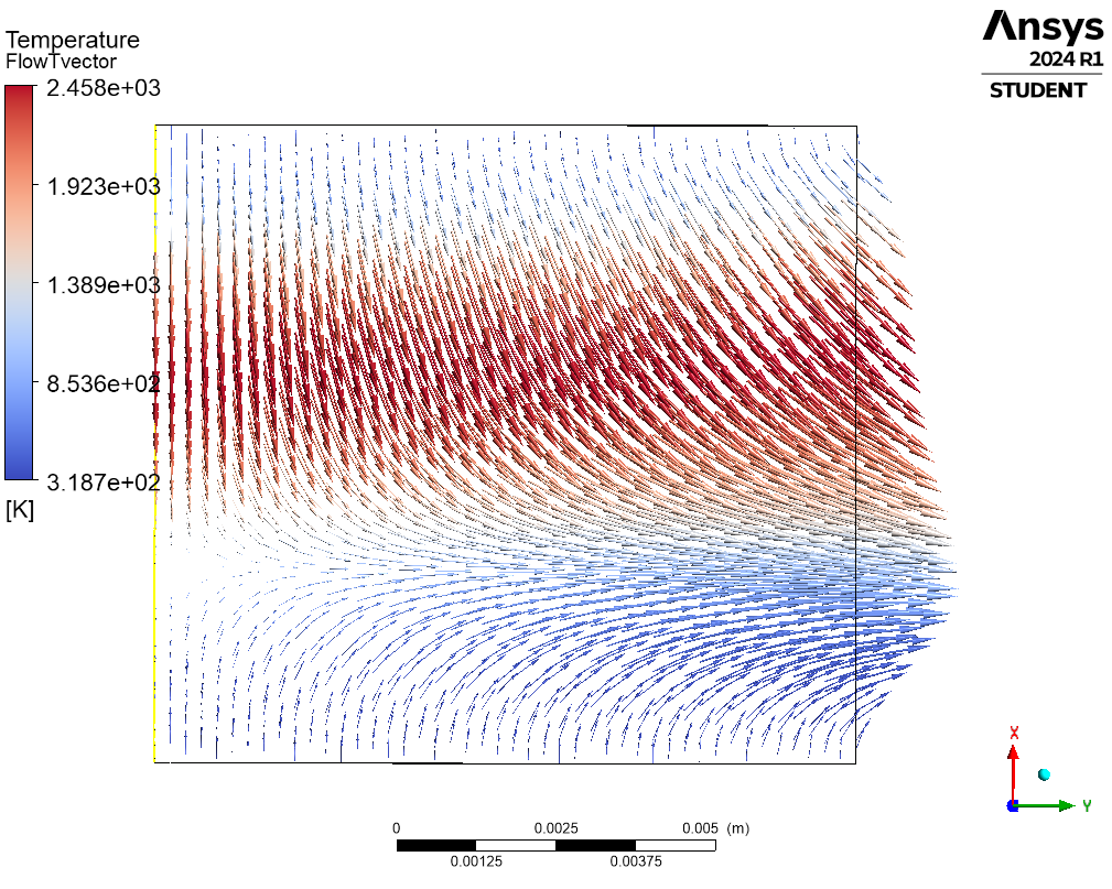
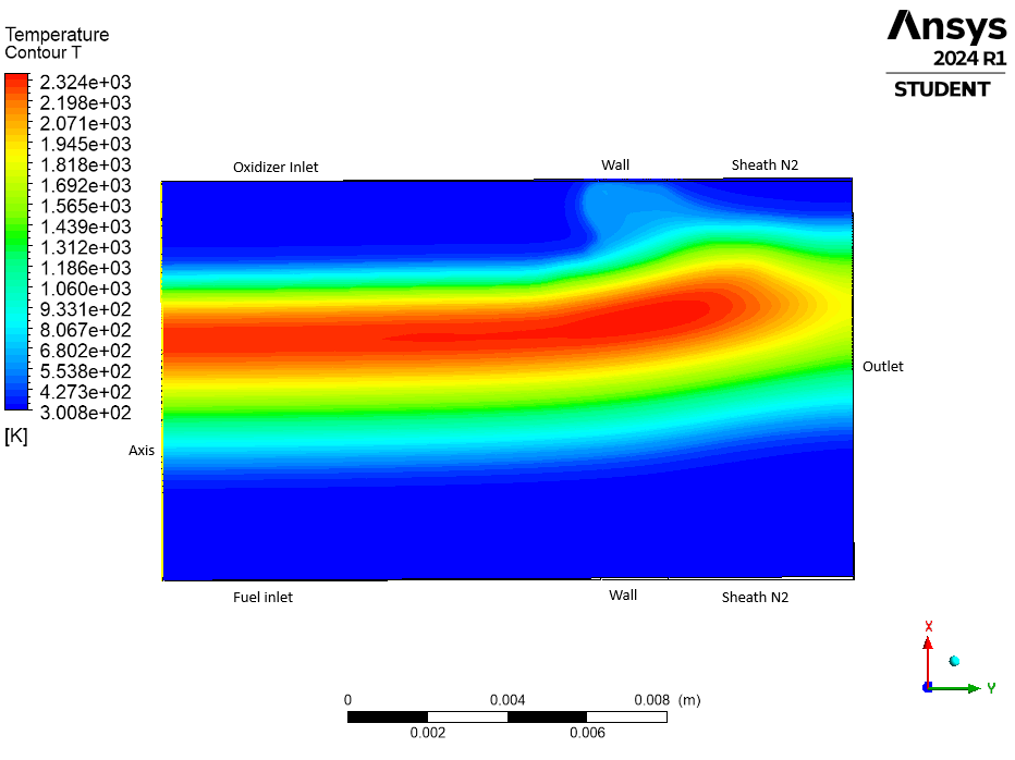
The flow and temperature for this counterflow diffusion flame are shown below.
- Left side: Axis of 2D axisymmetric domain (yellow)
- Bottom: Fuel inlet (velocity inlet)
- Top: Air inlet (velocity inlet)
- Right side: Outlet
Simulation overview:
- Fluent 2D axisymmetric; steady, laminar flow.
- Species transport with volumetric gas phase reactions: 30 species, 200 reactions, stiff chemistry solver.
- Species thermodynamic properties from Chemkin database, with multicomponent & thermal diffusion.
- Pressure-based solver; pressure-velocity coupled, Rhie-Chow distance-based flux type.
- Mesh 350 (X) by 45 (Y) rectangular grid, checked for mesh-independence.
Boundary condition details:
- fuel_inlet
- Velocity Specification Method: Magnitude, Normal to Boundary
- Reference Frame: Absolute
- Velocity Magnitude [m/s]: 0.2084
- Supersonic/Initial Gauge Pressure [Pa]: 0
- Temperature [K]: 318.7
- Specify Species in Mole Fractions? yes
- air_inlet
- Velocity Specification Method: Magnitude, Normal to Boundary
- Reference Frame: Absolute
- Velocity Magnitude [m/s]: 0.1125
- Supersonic/Initial Gauge Pressure [Pa]: 0
- Temperature [K]: 368.6
- Specify Species in Mole Fractions? yes
- outlet
- Gauge Pressure [Pa]: 0
- Pressure Profile Multiplier: 1
- Build artificial walls to prevent reverse flow? yes
- Average Pressure Specification? no
- Specify targeted mass flow rate: no
- axis
- axis: axis
-
February 16, 2024 at 4:26 pm
Rob
Forum ModeratorWhat did you set as the operating density? And don't use prevent reverse flow without a very good reason.
-
February 16, 2024 at 4:42 pm
Daniel Thomas
SubscriberThanks for the note, Rob. Under Setup > Materials > Mixture > chemkin-import the density is set to the incompressible-ideal-gas option.
Thanks for the note too about reverse flow; I've removed that, as there wasn't a good reason for that.
-
February 16, 2024 at 4:58 pm
Rob
Forum ModeratorOK, and if you're in Fluent, initialise the domain at the set outlet condition (ie some temperature, default is 300K) and then plot a contour of density on the domain with node values off. You should get a single value at about 1.1812345 kg/m3. That EXACT value is your operating density. If you check the Fluent User's Guide there's an explanation: you're avoiding the (rho - rho_operating) term on the boundary as it's now zero.
-
February 16, 2024 at 4:59 pm
Rob
Forum Moderatorhttps://ansyshelp.ansys.com/account/Secured?returnurl=/Views/Secured/corp/v241/en/flu_ug/flu_ug_bcs_sec_operating.html 7.3.1.5
-
February 16, 2024 at 8:30 pm
Daniel Thomas
SubscriberThank you for the note and reference, Rob. The current version of that documentation is clearer than the older version I saw online. I had not checked the Specified operating density option in Setup > Cell zone conditions > Operating Conditions. I accepted the default given, which was 1.225 kg/m3. However, the average density in the domain is much lower than this ~ 0.2 kg/m3 (between the hot flame zone and a hydrogen-based fuel), so I should probably try a lower value.
The PRESTO! option under Methods > Spatial discretization > Pressure also helped bring residual down.
I'm re-running it all now, and it looks like things are moving in the right direction...
-
February 17, 2024 at 3:57 pm
Daniel Thomas
SubscriberHi Rob, I also found a helpful case study on setting the operating pressure (/courses/wp-content/uploads/sites/2/2024/01/Tidbits-General-HT-Lesson-4.pdf), but I'm still unsure about the best setting here. This case is primarily forced flow, with buoyancy only altering the vertical position of the flame. As such, there should be no backflow; the flow continues radially outward confined by sheath gas flows. So while the far field density would be that of ambient air (300K), just outside the outlet boundary the density is the same as the outflowing gas -- which varies by an order of magnitude (0.1 - 1.0 kg/m3) vertically along the boundary.
- Would an outflow boundary condition be suitable? The documentation on natural convection flows focuses on pressure outlets, but with my fully developed incompressible flow, an outflow seems like a reasonable option. It doesn't seem like outflows are incompatible with bouyancy -- is that right?
- Should I set the operating pressure using an expression so that it is equal to the exiting gas density all along the outlet boundary?
Thanks again for your help with this.
-
February 19, 2024 at 1:51 pm
Ren
Ansys EmployeeHello,
Could you please tell me the following informaiton:
- The characteristic values that you used to calculate the Froude number
- The distance between the air and fuel inlets
- The velocity in the flame region
- How you define the flame position
-
February 19, 2024 at 4:44 pm
Daniel Thomas
SubscriberHi Ren,
Thanks for the note. Responding to your questions:
- For the case shown in my first post above, the inlet conditions are below. Calculating a Froude number from the mean of the outlet velocities gives Fr = 0.26. I’m interested in flames with higher outlet velocities (and Fr >1), but am using this case to make sure that the buoyancy effects are modelled correctly.
- Fuel outlet (lower): v_f = 0.208 m/s, T_f = 319 K, X_f = {‘NH3’ : 0.35, ‘H2’: 0.65} (mole fractions)
- Oxidizer outlet (upper): v_o = 0.113 m/s, T_o = 368 K, X_o = {‘N2’: 0.79, ‘O2’: 0.21}
- The distance between inlets is 10 mm, and the domain extends radially outward in y by 11 mm.
- The flow vector plot above gives a picture of velocities in the flame region, with significantly higher radial velocities at the outlet.
- The flame position can be mostly simply defined by the peak temperature. However it is defined, experimental observations and literature on this type of counterflow flame indicate that buoyancy should act to shift the flame for lower velocity flames as in this case.
I look forward to hearing any suggestions you have or any feedback on my questions above. Thanks!
- For the case shown in my first post above, the inlet conditions are below. Calculating a Froude number from the mean of the outlet velocities gives Fr = 0.26. I’m interested in flames with higher outlet velocities (and Fr >1), but am using this case to make sure that the buoyancy effects are modelled correctly.
-
February 20, 2024 at 11:24 am
Ren
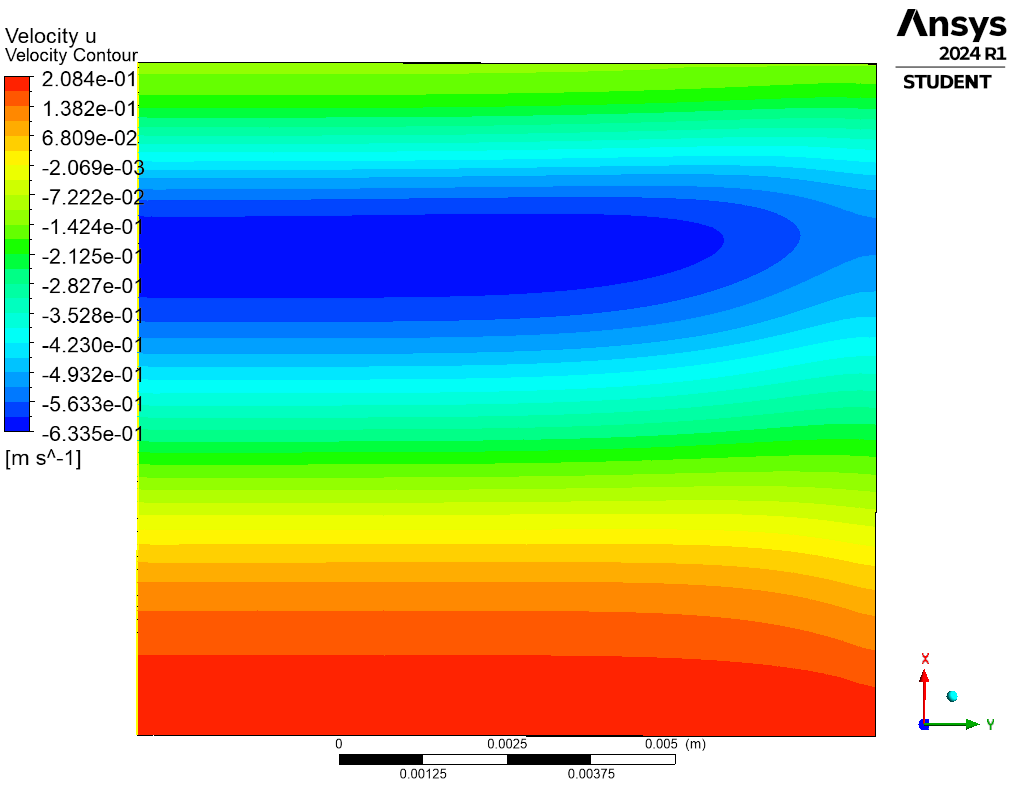
Ansys EmployeeCan you please show me a velocity contour plot?
-
February 20, 2024 at 10:15 pm
-
February 21, 2024 at 3:55 pm
Ren
Ansys EmployeeHello, Daniel,
It can be seen from the velocity contour plot that a representative value of velocity is u = 0.5 m/s (or even larger) in the flame region. The Froude number based on this value is
Fr = 0.5 / sqrt(9.81 * 0.01) = 1.60
A more representative length scale would be the width of the flame region. Based on the temperature field, this can roughly be estimated as, L = 0.01 m / 3 = 0.0033 m. The Froude number based on this length scale is
Fr = 0.5 / sqrt(9.81 * 0.0033) = 2.78
This explains why the flame position is not affected much by the gravity.
-
February 21, 2024 at 4:23 pm
Daniel Thomas
SubscriberHi Ren,
Thank you for the response. As you indicate, the Froude number can be calculated in a variety of ways. In the literature on counterflow diffusion flames it is typically calculated using the outlet velocity and the nozzel separation distance, as I have done. I could change the test case to reduce the outlet velocity further, but based on experimental observations (my own and others reported in the literature), buoyancy effects should be discernable at these velocities. (Still a small effect, but discernable.)
My reason for posting was to make sure that my boundary conditions were suitably defined to give me confidence in the validity of these 2D simulations. Adding a density operating condition, as Rob suggested, does result in a flame position shifted from the 1D model and my previous results. However, I'm not sure I have that defined correctly. Did you have any thoughts on the questions I mentioned above?
- Would an outflow boundary condition be suitable? The documentation on natural convection flows focuses on pressure outlets, but with my fully developed incompressible flow, an outflow seems like a reasonable option. It doesn't seem like outflows are incompatible with bouyancy -- is that right?
- Should I set the operating pressure using an expression so that it is equal to the exiting gas density all along the outlet boundary?
Thanks again for your help with this.
-
February 22, 2024 at 10:27 am
Ren
Ansys EmployeeHello, Daniel,
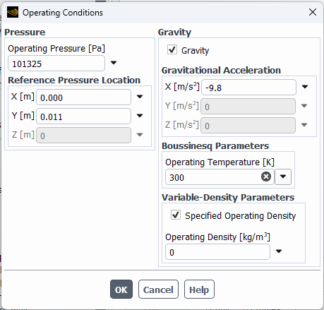
- Yes, I think you should be able to use the Outflow condition. I suggest that you set the Operating Density (OD) to zero and the Reference Pressure Location (RPL) at a point on the outlet, say, the bottom of the outlet boundary. You should also investigate the effect of the domain horizontal size on the flame position. I guess you are comparing the flame vertical position at a specific horizontal coordinate value. So, you should also investigate the effect of the mesh resolution in the vertical direction.
- No, keep the Operating Pressure (OP) at a constant value.
-
February 23, 2024 at 10:12 pm
Daniel Thomas
SubscriberHi Ren,
Thank you for your note and suggestions. I'm running it now with an outflow BC, the operating density set to zero, and the RPL at the base of the outlet boundary, as you suggest (see below); so will write again when I have those results.
I see I wrote 'operating pressure' in my second question, when I meant to ask about setting the operating density as an expression. But if the operating pressure = 0 approach works, then that is simpler.
Thanks too for the notes about the mesh effects. I've did an initial grid study, but will have to return to it after getting the BCs correct. And yes, I'm just interested in the centerline (x axis) values for temperature, species, etc.
-
April 19, 2024 at 10:17 pm
Daniel Thomas
SubscriberHi Ren,
Following up on this, with another question. I ended up extending the domain in the y-direction to include the adjacent wall and sheath flow inlets, and repeated my mesh study to check the effect of refinement in the y-direction. With a refined grid, I was able to see the expected slight upward shift in the flame with conditions of slow flow and exaggerated gravity. Very nice to have that result -- and thank you for your help.
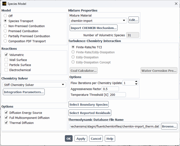
However, for flow rates corresponding to my experimental conditions, I am seeing peak temperatures almost 100 K higher than expected -- even with substantial grid refinement. I'm solving the energy equation with volumetric reactions using an imported mechanism. I've included the species transport inputs below. I didn't find any tutorial exactly matching this. Are you aware of any? I'd be particularly interested in any that includes radiation for this gas-phase (no soot) flame.
-
April 22, 2024 at 2:53 pm
Ren
Ansys EmployeeHi, Daniel,
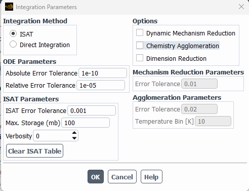
The setup in the Species Model dialog box look fine. Could you also show me the Integration Parameters dialog box? What is the fuel? What chemical mechanism is used?
-
April 22, 2024 at 3:20 pm
Daniel Thomas
SubscriberHi Ren - Thanks for the note; the Integration Parameters are below. I have not used ISAT before this project with Fluent, and the settings there are default. Do you think I should reduce the ISAT tolerance?
The fuel is a mix of 65% H2, 35% NH3, molar basis, and I'm using a mechanism from Stagni et al, 2020, which is currently one of the better ones available for predicting N-H-O reactions in ammonia combustion (31 N-H-O species, 203 reactions, https://pubs.rsc.org/en/content/articlelanding/2020/re/c9re00429g ).
-
April 23, 2024 at 2:20 pm
Ren
Ansys EmployeeHi, Daniel,
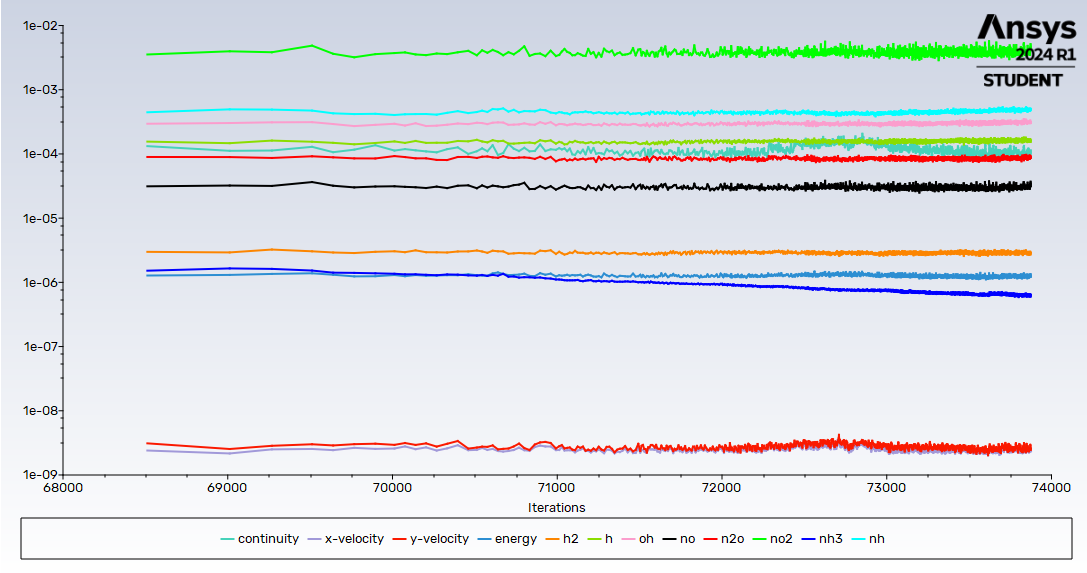
The settings are fine. What is the energy equation residual looking like? Is it small enough?
-
April 23, 2024 at 8:16 pm
Daniel Thomas
SubscriberHi Ren,
Thanks for the note. The residuals plot is below, showing energy at about 1e-6. The only residuals that remain higher are the minor species, such as NO2, which are present in very low ppm levels. This particular simulation seems fine from the residuals, but is waiting for total energy and temperature parameter to steady out. Any ideas on other things to check?
-
April 24, 2024 at 10:16 am
Ren
Ansys EmployeeI can't think of anything obvious but you could try the following, one-by-one, for investigation purpose:
- Reduce ISAT Error Tolerance to, 1E-4, then 1E-5
- Disable Thermal Diffusion
- Disable Multicomponent Diffusion
-
April 24, 2024 at 1:30 pm
Ren
Ansys EmployeeCould you please try the following first:
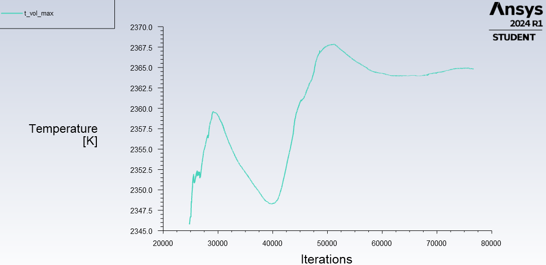
- Define a monitor for max temperture in the domain, run the existing calculation further to check if the max T is still changing.
- Activate the DO radiation model, set the absorption coefficient method to wsggm-domain-based for the mixture material.
-
April 24, 2024 at 2:38 pm
Daniel Thomas
SubscriberHi Ren -- Thanks for these suggestions. I have been monitoring a maximum Temp variable, which does take a while to steady out (as do the average Temp and total energy variables) -- see below. For this current run, I'll continue to allow these to stabilize some more, although the current variation (~2K) is much less than the difference from expected temperature profile (~100 K).
Thanks for the suggestion on the radiation model; that was something I was going to ask you about. For this fairly high temp flame it should be significant though probably not accounting for the whole existing discrepency. I'll be in touch once I've tried that.
-
- The topic ‘BCs for buoyant flow with outlet parallel to gravity vector’ is closed to new replies.


-
5059
-
1764
-
1387
-
1248
-
1021

© 2026 Copyright ANSYS, Inc. All rights reserved.

