TAGGED: 3DFDTD, bandstructure, effective-index, lumerical, Lumerical-FDTD, script, simulation
-
-
May 22, 2024 at 1:02 pm
minusunny
SubscriberHi,
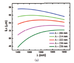
I am trying to get a graph like below from a reference paper.
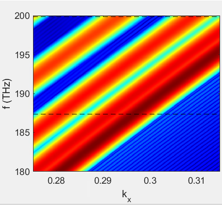
If this graph is correct my difference in effective index of first and fundamental order mode is around 0.013. I am trying to do the simulation given in this one https://www.lumerical.com/learn/video/swg-bandstructures/ . My k vector points at 222 nm pitch and 8 um wide SWG unit cell was found to be around 0.306 for fundamental mode and 0.29 for the first order mode. I gave k vector range around 0.27- 0.32. The effective index calculation differs so much, even if i tried sweeping for 10, 50,100,500 points. What can be the possible issue for the huge effective index, is it the range of f1 and f2 provided or is it the range of k vector values? I did all the simulation by keeping 10 nm mesh size. I haave attached the band diagram and the simulation file as well.
https://drive.google.com/file/d/1BdtTeoE0gD9E_uPQyTD2py2o_nWDIagy/view?usp=sharing
-
May 22, 2024 at 11:23 pm
Amrita Pati
Ansys EmployeeHi Minu,
Thanks for sharing the link. I haven't worked on this example, I will have a look and come back to you.
Regards,
Amrita -
May 23, 2024 at 9:50 pm
minusunny
SubscriberThank you.
-
May 24, 2024 at 6:03 pm
Amrita Pati
Ansys EmployeeHi Minu,
I was traveling yesterday and didn't have a lot of time to look into this. But I did consult with my colleague. One of the reasons behind the discrepancy could be the time signal. Initially we excite all the modes of the geometry, some of these modes (non-resonant modes) would die down, but the modes that sustain will be the resonant modes (modes of interest), and we can calculate their effective indices. It is possible that, in your simulation, the analysis group is choosing a non-resonant mode.
One thing we can do is run the simulation long enough for the non-resonant modes to decay completely. What you can do it turn off the auto shutoff termination (uncheck use early shutoff unchecked in the Advacned Options of FDTD), and run the simulation for a longer amount of time. It is hard to tell by how much longer, I will say increase the time by 20% a couple times and check if you see any differences.
Regards,
Amrita -
May 24, 2024 at 6:48 pm
minusunny
SubscriberThanks,I will try this and let you know.
Minu
-
- The topic ‘Band structure simulation FDTD’ is closed to new replies.


-
3407
-
1057
-
1051
-
896
-
877

© 2025 Copyright ANSYS, Inc. All rights reserved.


