TAGGED: baja-sae, SAE-Chassis
-
-
October 3, 2024 at 2:05 am
osirizd
SubscriberHello, I have a chassis that's not able to solve. Here are the errors I've encountered.
One or more MPC or Lagrange Multiplier formulation based contact regions or remote boundary conditions may have conflicts with other applied boundary conditions or other contact or symmetry regions. This may reduce solution accuracy. For MPC based remote points, setting the relaxation method may help eliminate overconstraint. Tip: You may graphically display FE Connections from the Solution Information Object for non-cyclic analysis. Refer to Troubleshooting in the Help System for more details.The maximum contact stiffness is too big. This may affect the accuracy of the results. You may need to scale the force unit in the model.An overlap is detected between one or more contact regions and boundary condition(s) applied to your model. Hence Augmented Lagrange formulation is used as the Program Controlled option for those contacts.Some of the elements on the problematic bodies can't meet the specified target metrics. Please check the elements and try changing the mesh size settings to achieve the needed mesh quality.
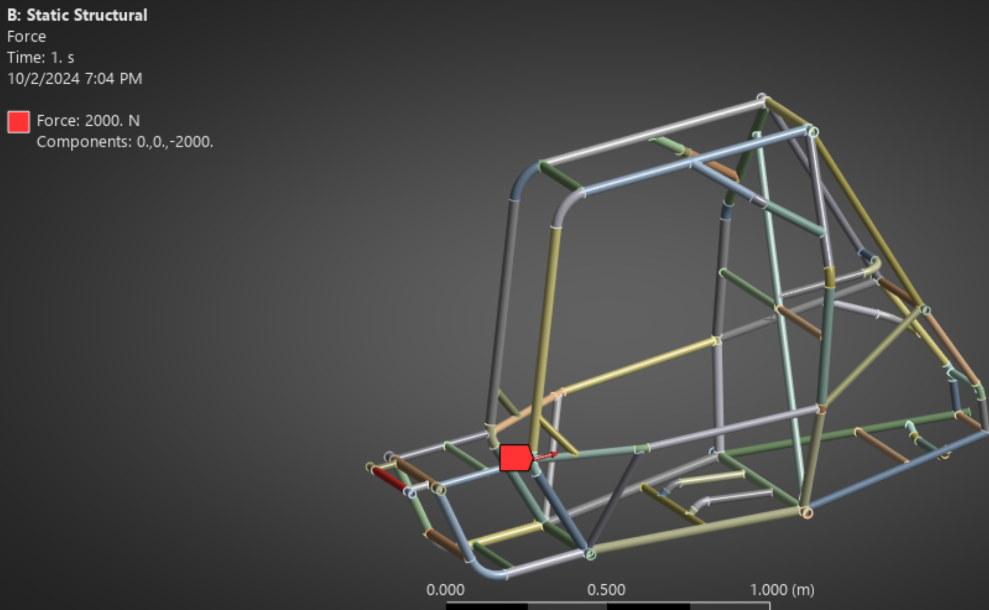
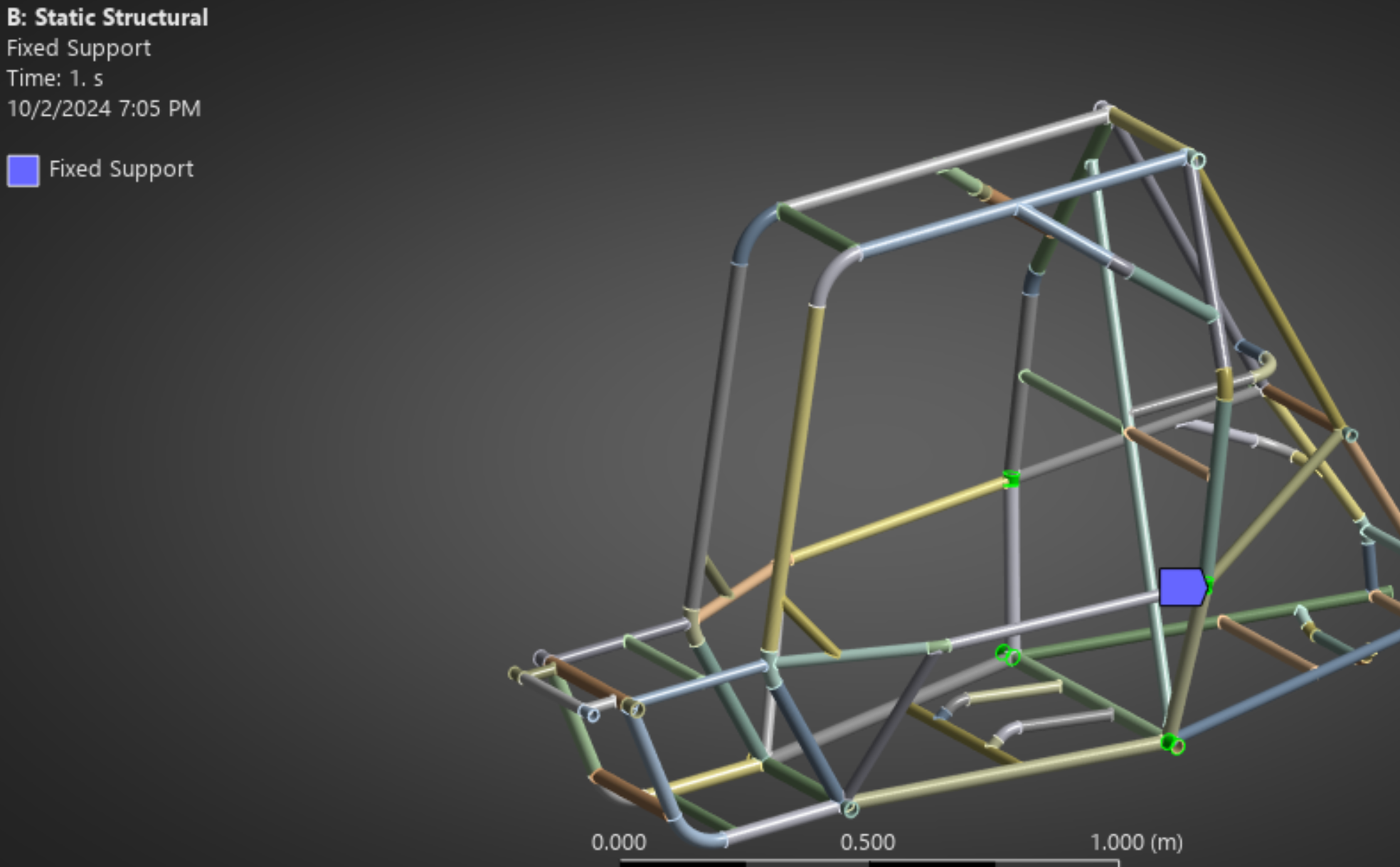
I've ran my model on Discovery and fixed any and all of the gaps and wrong geometry it can fix in the Repair ribbon tab. It did make a successful mesh but It couldn't solve it. Any tips? Below are pictures of my applied loads.
-
October 4, 2024 at 9:19 am
Kaushal Vadnere
Ansys EmployeeHello,
From looking at the image you've shared, I believe you are performing this simulation using solid elements. The members of the chassis are slender bodies and hence modelling the chassis using 1D beam formulation would be better than using 3D solid elements. Having inadequately discretized solid mesh would result in poor mesh quality and ultimately convergence issues. You can also see that in the 4th warning message you've shared (Some of the elements on the problematic bodies can't meet the specified target metrics. Please check the elements and try changing the mesh size settings to achieve the needed mesh quality.) Having a good quality mesh with solid elements would require finer element size and this would increase element/node count by a huge margin. this will not only reduce efficiency but may also exceed the problem size limits in case you are using student version of Ansys.
Hence, I would suggest you to run your simualtion with beam elements. We have a FREE full length self-paced course on Baja SAE chassis analysis on Ansys Innovation Space. You can find the link to it here: BAJA SAE Chassis Analysis | Ansys Innovation Courses. It covers everything from scratch (geometry prep, meshing, analysis, etc). Once you are done with static analysis, you can continue with dynamic analysis of the chassis by refering to another free course by ansys here: BAJA SAE Chassis Dynamic Analysis Using Ansys Mechanical | Ansys Courses.
Also, FYI -
For your 1st error/warning message regarding MPC contacts,
- You can find various troubleshoot options for this message in this article from Ansys Help document here: One or more MPC or Lagrange Multiplier formulation based contact may have conflicts (ansys.com)
For the 2nd error/warning message regarding contact stiffness,
- This is a limitation of penalty based contact. This warning occurs when normal contact stiffness (FKN) is higher than 10^16. To remove this issue we need to change the “unit system” in Mechanical. By defaults the unit of normal contact stiffness (FKN) is FORCE/LENGTH^3. If we change the (m kg N..) unit system to (mm kg N..) unit system the new FKN value will be 10^(-9) times the previous one. You may also try to change the contact algorithm. -
September 2, 2025 at 5:12 pm
pro.skillslearner
SubscriberIt looks like you’re running into a combination of overconstraints and mesh quality issues. The errors about MPC/Lagrange conflicts and maximum contact stiffness usually point to boundary conditions fighting each other. Sometimes switching a few contacts to “frictionless” or adjusting stiffness scaling can help.
For the overlap warning, double-check that none of your boundary conditions are applied directly on the same faces as your contacts. Even a small mismatch can cause the solver to switch to Augmented Lagrange and create instability.
On the meshing side, reducing element size locally (especially near contact regions) instead of globally can make a big difference. I’ve also seen people get better stability by simplifying the geometry even more before applying the mesh.
If you want to take a break from debugging and need something lighter, I recently came across this dog to human years calculator that shows how our pets age compared to us — pretty neat little tool.
Have you tried running the same setup with a coarser mesh first just to test if it solves, then refining later? Sometimes that reveals if the issue is purely with the mesh density or if it’s really the constraints.
-
- You must be logged in to reply to this topic.
- Fluent: Setup is missing Models, Cell Zone, Boundary Conditions in Student
- BAJA Chassis not Solving
- How Ansys Solver Derives Coefficients in Tsai-Wu Failure Criterion
- Unable to Save Animation (HSF or AVI) Automatically in Fluent During HPC RUN
- Fusible Link Simulation
- Local Refinement in Ansys fluent
- Free Faces in 3D CFD for formula student car
-
3817
-
1388
-
1188
-
1100
-
1015
© 2025 Copyright ANSYS, Inc. All rights reserved.